Table of Contents
Advertisement
Quick Links
Advertisement
Table of Contents

Subscribe to Our Youtube Channel
Related Manuals for Whadda WSAH8060


Summary of Contents for Whadda WSAH8060
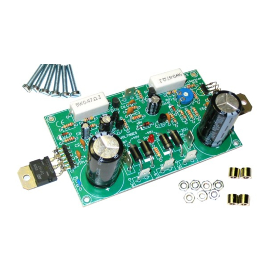
- Page 1 ILLUSTRATED ASSEMBLY MANUAL 200W DISCRETE POWER AMPLIFIER WSAH8060 whadda.com...
-
Page 2: Specifications
Features & Specifications Specifications: Excellent value for money Full discrete design using Epitaxial Darlington transistors DC supply circuit on board with LED indication Ideal for active speaker system or sub woofer, guitar amp, home theatre systems, instruments amp…. ... -
Page 3: Assembly Hints
Assembly hints 1. Assembly (Skipping this can lead to troubles ! ) Ok, so we have your attention. These hints will help you to make this project successful. Read them carefully. 1.1 Make sure you have the right tools: • A good quality soldering iron (25-40W) with a small tip. - Page 4 Assembly hints 1.3 Soldering Hints : 1- Mount the component against the PCB surface and carefully solder the leads 2- Make sure the solder joints are cone-shaped and shiny 3- Trim excess leads as close as possible to the solder joint REMOVE THEM FROM THE TAPE ONE AT A TIME ! AXIAL COMPONENTS ARE TAPED IN THE CORRECT MOUNTING SEQUENCE !
-
Page 5: Resistor Color Code
DIGITS Multiplier Tolerance RESISTOR COLOR CODE stripe 4th stripe Black 10K OHM +/- 1% Brown x 10 digit x 100 digit Orange x 1 000 digit multiplier Yellow x 10 000 tolerance Green x 100 000 Blue x 1 000 000 100K OHM +/- 5% Purple... - Page 6 Construction 1. Diodes. Watch the polarity ! 4. Transistor connections ❑ R3 : 3K3 (3 - 3 - 2 - B) ❑ R4 : 330 (3 - 3 - 1 - B) ❑ R5 : 220 (2 - 2 - 1 - B) ❑...
-
Page 7: Electrolytic Capacitors
Construction & connection 7. Trim potentiometer 5. Power diodes. 10. PCB tabs. Watch the polarity ! ❑ RV1 : 1K ❑ IN ❑ D3 : 1N5404 ❑ GND ❑ D4 : 1N5404 ❑ D5 : 1N5404 D... ❑ D6 : 1N5404 CATHODE 11. - Page 8 Construction 13. 5W resistors R... ❑ R19 : 0,47 ❑ R20 : 0,47 IMPORTANT 14. Electrolytic Capacitors. Watch the polarity ! Check the complete assembly carefully before mounting the heat sink. ❑ C12 : 3300µF ❑ C13 : 3300µF ...
-
Page 9: Final Assembly
Final Assembly 15. Final assembly A custom pre-drilled heat sink is available from your distributor (order code HSVM100). Any other heat sink must be able to dissipate at least 30W (1.25°C/W) (see fig.1.0). Use the template as a drill guide Fig. - Page 10 Final assembly • • Mount 4 bolts + 8 nuts (PCB support). (fig.2.0) Slide the PCB over the 4 bolts, and fix using 4 nuts (Fig 3.0). 2 x M3 nut Fig. 3.0 M3 15mm bolt Fig. 2.0...
- Page 11 Transistor T6 16. Mounting the transistor T6 on the heat sink: • Apply a drop of heat conductive compound in the heat sink hole (fig. 4.0). Fig. 4.0...
- Page 12 Transistor T6 • Insert the transistor (BC547) in the hole (Fig. 5.0). Pay attention to the position of the transistor (fig 6.0)! BC547 Fig. 5.0 Fig. 6.0 • Carefully bend the leads and solder them to the connector T6, see figure 7.0.
- Page 13 Power transistors 17. Mounting of the power transistors T7 (TIP147) and T8 (TIP142). M3 nut • Apply a drop of heat conductive compound on the heat sink (see fig 8.0.) Lock washer washer • plastic isolation Mount the isolation mica onto the heat sink, check the position of the hole. washer Apply a drop of heat conductive compound on the mica.
- Page 14 Power transistors • Solder the connections of the power transistors with the pin headers, see fig. 10. Fig. 10...
- Page 15 Test & adjustments 18. Test and adjustments • Use a 2 x 25 to 30Vac / 100 - 120VA transformer. • Connect the transformer to the AC power connections of the PCB. • The Velleman transformer colour scheme is specified on the pcb. ...
- Page 16 Test & adjustments...
- Page 17 Test & adjustments • Turn the RV1 bias adjust trimmer fully counter clockwise (turn left) before applying power for the first time. ADVICE: For safe first-time testing insert a 60W light bulb in series with the AC power and the transform- er.
- Page 18 Test & adjustments Final connection: • The input (GND and in) can be connected directly to an audio source (pre-amp or mixing panel) or a vol- ume control (potentiometer) can be used (see diagram). • Connect the speaker (4 ohm or higher) to the connections LS+ and GND. ...
- Page 19 Diagram 19. Diagram +40 V +40 V 1N 54 04 +40 V 33 K 10 0n F 47 00 µ/5 0V AC-0 1N 54 04 68 0p 1K 5 AC-0 TIP1 42 LD 1 GN D GN D LE D3 RL 1N 54 04 10 0n F 47 00 µ/5 0V...
- Page 20 Modifications and typographical errors reserved. © Velleman Group nv, Legen Heirweg 33 - 9890 Gavere (België) WSAH8060 - 09082021...
Need help?
Do you have a question about the WSAH8060 and is the answer not in the manual?
Questions and answers