
Related Manuals for CARLO GAVAZZI EcoEnergy WT3-BC

Summary of Contents for CARLO GAVAZZI EcoEnergy WT3-BC
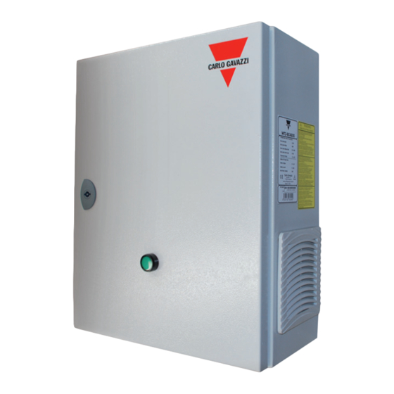
- Page 1 CARLO GAVAZZI A u t o m a t i o n C o m p o n e n t s WT3-BC 48V Battery Charger for Wind Turbine Stand Alone System User Manual...
- Page 3 WT3–BC User Manual Version Date Author Description 10-06-2011 Stefano Fusetti First release 21-06-2011 Stefano Fusetti Anemometer description Battery charging process & braking system 05-09-2011 Stefano Fusetti updated. 24-11-2011 Stefano Fusetti Wind turbine connection updated 13-12-2011 Stefano Fusetti Thermal compensation updated Communication interface pinout and 06-02-2012 Stefano Fusetti...
-
Page 4: Intended Use
Intended use This manual must be read and used by both the installer and the end user. The aim of this technical documentation is to provide the necessary information required to install and use the battery charger WT3-BC, as well to define the function, usage and command modes. -
Page 5: General Safety Instructions
General safety instructions Only trained and qualified personnel are authorised to mount, reconfigure and repair this battery charger; Only licensed electricians are entitled to permanently install wired equipment; All safety instructions and information contained in the present manual must be carefully read and followed;... -
Page 6: Connection To The Wind Turbine (Ac)
Connecting the temperature sensor (Carlo Gavazzi Tempsol 1000) The temperature sensor (recommended Carlo Gavazzi Tempsol 1000) must be placed directly onto the battery. Connect the two pins of the Tempsol 1000 to the terminal board of the battery charger. Tempsol 1000 has no polarity, so one pin must be connected to the mass terminal block –... -
Page 7: Repair And Maintenance
Repair and Maintenance Only Carlo Gavazzi Logistics S.p.A. personnel are authorized to repair this unit. Warning Never try to alter or modify the assembly of the battery charger: you may incur an electric shock. Caution Attempted repairs carried out by unauthorized people may permanently... -
Page 8: Table Of Contents
Battery charger wiring ......................... 4 Connection to the wind turbine (AC) ....................5 Connection to the battery (DC) ......................5 Connecting the temperature sensor (Carlo Gavazzi Tempsol 1000) ........... 5 Repair and Maintenance ........................6 Product overview ..........................8 WT3-BC Main Functions......................... 8 Package Content ........................... -
Page 9: Product Overview
Product overview The WT3-BC is a battery charger designed for stand-alone wind power plants. Figure 1 shows the required connections of the battery charger in order to commission the plant. The battery charger is connected to the wind turbine, and delivers the energy, converted into DC, to the battery to keep it charged. -
Page 10: Package Content
Package Content The package contains: - battery charger 1 pc; - resistor box 1 pc; - communication cable 1 pc; - user manual 1 pc. Battery charger location The WT3-BC is designed for vertical mounting, and is suitable for either indoor or outdoor installation. -
Page 11: Battery Charger Wiring
Battery charger wiring All the connections to the unit must be made using the terminal board shown in figure 3: Clamp label Element to be connected Turbine phase Turbine phase Turbine phase Ground cable Braking resistor Braking resistor Braking resistor BAT + Positive battery terminal BAT -... -
Page 12: Resistive Brake Connection
(each resistor is able to dissipate an electrical power of 1 kW). The Carlo Gavazzi resistors are placed in a specific box, called a braking box (part number WT3RB12), which must be connected to the battery charger via the terminal board using PVC insulated, stranded copper wires, of at least 4 mm section. -
Page 13: Temperature Probe And Anemometer
14 (mass) and 15 (signal) - for measuring the wind speed. The wind speed measure is used to verify the performance of the battery charger. Several kinds of anemometers can be used: the battery charger can read signals such as those of the Carlo Gavazzi DWS-V- DBC05 anemometer, which has the following characteristics: square wave output signal;... -
Page 14: Battery Connection
Battery connection The battery charger has been optimized for a battery charging capacity of 1000 Ah, but also ensures high performance with battery capacities in the range of 500 - 1200 Ah. For this connection you must use the dedicated terminal board: the wires to be used should have a section of at least 16 mm if only one cable for each pole is used.Two cables of 8 mm... - Page 15 Warning All electrical work must be carried out in accordance with the local and national electrical norms, and should follow all the safety precautions contained in this manual. Warning Make sure suitable cables are used for both AC and DC connections. The cables must be of the correct size (see the connections paragraphs) and must be resistant to temperature fluctuations, to UV radiation and other possible hazards.
-
Page 16: Mppt Algorithm
MPPT algorithm The MPPT ( Maximum Power Point Tracking ) algorithm maximizes the energy conversion in all working conditions of the wind turbine. This is implemented by continuously adapting the current load on the turbine and verifying the voltage stability. The optimal curve –... -
Page 17: Short Circuit Brake
Short circuit brake The short circuit brake is a safety brake: it is activated when the turbine is wired to the battery charger (see relevant chapter), the general AC three-phase breaker is in ON position and the battery charger is OFF. In this way the maximum electrical load (is applied to the wind turbine), which is the maximum braking. -
Page 18: Battery Charging Process
Battery charging process Control of the battery charging, in order to extend the battery lifetime above the average, is performed using the I.C.C. (Interrupted Charge Control) technique, which avoids gas evaporation. The I.C.C. technique charging process is performed in two phases: the bulk charge and the interrupted charge. -
Page 19: Braking, Load Relay Command, Overcharging And Ac Overvoltage Protection Thresholds
Braking, load relay command, overcharging and AC overvoltage protection thresholds Resistive braking thresholds The braking control system activates or deactivates the resistive brake depending on the value of the rectified voltage, which is connected to the thresholds listed in table 4: Threshold Rectified voltage [V] AC voltage [V]... -
Page 20: Local Load Control Relay (Rcm) Thresholds
Local load control relay (RCM) thresholds The status of the command for the local load relay depends on the battery voltage: Threshold Battery voltage [V] Load activation (OFF ON) 50.4 Load deactivation (ON OFF) 45.6 Table 5: load relay command thresholds. The control unit sets the local load relay command according to the value of the battery voltage, which is connected to the thresholds listed in table 5. -
Page 21: Battery Overcharging Protection Thresholds
Battery overcharging protection thresholds To avoid overcharging of the battery, when the battery voltage exceeds a defined threshold the resistive brake is switched on, in order to deliver the power coming from the wind turbine to the brake; in this way the battery charging process is interrupted. When the battery voltage drops below a reactivation voltage the resistive brake is switched off and the battery charging process is restarted. -
Page 22: Wind Turbine Overvoltage Protection
Wind turbine overvoltage protection To avoid overvoltage from the wind turbine, a protection system disconnects the battery charger from the wind turbine if the AC voltage exceeds a fixed value, and is reconnected only when the AC voltage drops below a safety threshold (see table 8): Threshold WT AC voltage [V] (phase-phase) WT overvoltage protection (OFF ... -
Page 23: Wind Turbine Curve
Wind turbine curve The battery charger is supplied with a pre-charged wind turbine curve. This is the curve of the Carlo Gavazzi Mistral wind turbine, a 3 kW wind turbine, as shown in the next figure: Figure 9: wind turbine curves. -
Page 24: User Interface
User interface The WT3-BC can interact with the operator in two ways: by means of the display and by the three LEDs placed on the top of the display. The status (on, off or blinking) of the LEDs indicates the battery charging process status, whilst the display is used to visualize the different values of the plant or the active alarms. -
Page 25: Display
Display The WT3-BC has a display, which is used to visualize the measurements on the system and the active alarms. In order to simplify the navigation of the information on the display, measurements and alarms are collected in two different sub-menus, which may be browsed by using the pushbuttons on the right side and below the display. - Page 26 Figure 11: hierarchy and browsing of the menus.
-
Page 27: Measurements
Measurements The table below shows the list of measurements that can be displayed on the device display: Measure Displayed message Current from wind turbine [A] WT input current Rectified voltage from wind turbine [V] WT input voltage Electrical power from wind turbine [W] WT input power RMS voltage (ac) from the wind turbine [V] WT ac voltage... -
Page 28: Communication Interface
Communication interface The WT3-BC is equipped with two serial RS232 / RS485 communication ports. The cable must be a shielded communication cable EIA/TIA T568A (8 wires), as in the following picture: Figure 12: serial communication cable: PC (or converter) side (on the left) and battery charger side (on the right). -
Page 29: Technical Specifications
Technical specifications AC input (wind turbine) 55 – 300 V Voltage input range 0 – 10 A Current input range Maximum input electrical power 3.000 W Voltage threshold for activating the resistive brake. 230 Vrms (phase to phase) 20 – 180 Hz Input frequency range Turbine over-voltage threshold 270 Vrms (phase to phase) -
Page 30: Device Electrical Wiring Diagram
Device electrical wiring diagram... - Page 31 Note Note...
- Page 32 Over Hadstenvej 40, DK-8370 Hadsten NORWAY - Carlo Gavazzi AS Tel: +45 89 60 6100 GREAT BRITAIN - Carlo Gavazzi UK Ltd Melkeveien 13, N-3919 Porsgrunn SWITZERLAND - Carlo Gavazzi AG Fax: +45 86 98 15 30 7 Springlakes Industrial Estate,...
Need help?
Do you have a question about the EcoEnergy WT3-BC and is the answer not in the manual?
Questions and answers