Advertisement
Quick Links
OPERATING INSTRUCTIONS AND
SYSTEM DESCRIPTION FOR THE
INT-20X-USB
BREAKOUT BOX
FOR RECORDING AND GENERATING
ELECTRICAL SIGNALS
VERSION 1.6
npi 2023
npi electronic GmbH, Bauhofring 16, D-71732 Tamm, Germany
Phone +49 (0)7141-9730230; Fax: +49 (0)7141-9730240
support@npielectronic.com; http://www.npielectronic.com
Advertisement

Related Manuals for NPI INT-20X-USB

Summary of Contents for NPI INT-20X-USB
- Page 1 OPERATING INSTRUCTIONS AND SYSTEM DESCRIPTION FOR THE INT-20X-USB BREAKOUT BOX FOR RECORDING AND GENERATING ELECTRICAL SIGNALS VERSION 1.6 npi 2023 npi electronic GmbH, Bauhofring 16, D-71732 Tamm, Germany Phone +49 (0)7141-9730230; Fax: +49 (0)7141-9730240 support@npielectronic.com; http://www.npielectronic.com...
-
Page 2: Table Of Contents
INT-20X-USB – User Manual Table of Contents 1. Safety Regulations ......................3 2. INT-20X-USB Breakout Box ..................... 4 2.1. System Description ...................... 4 2.2. Parts Shipped with the Breakout Box ................4 2.3. Description of the Front Panel ..................5 2.4. -
Page 3: Safety Regulations
(e.g. for diagnosis or treatment of humans), or for any other life-supporting system. npi electronic disclaims any warranties for such purpose. Equipment supplied by npi electronic must be operated only by selected, trained and adequately instructed personnel. -
Page 4: Int-20X-Usb Breakout Box
INT-20X-USB – User Manual 2. INT-20X-USB Breakout Box 2.1. System Description The INT-20X-USB is a universal multifunction I/O interface with a built-in USB board (NI USB-6221 OEM) from National Instruments. The standard data acquisition system consists of the INT-20X-USB breakout box and software to record up to 16 analog signals with 16 bit resolution and store the data on hard disk. -
Page 5: Description Of The Front Panel
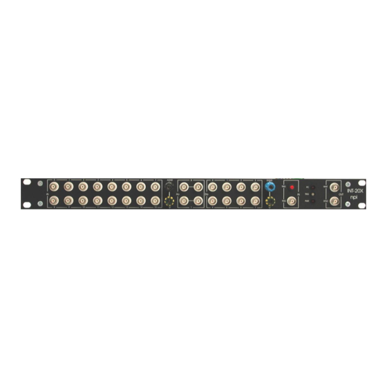
INT-20X-USB – User Manual 2.3. Description of the Front Panel Figure 1 shows the INT-20X-USB front panel. Table 1 includes a short description of all front panel elements. The names in brackets are the signal denotations used in the User Manuals from National Instruments. - Page 6 CellWorks (see Figure 2). Note: STARTSCAN is set by hardware and therefore precise. Table 1: front panel elements of the INT-20X-USB breakout box ___________________________________________________________________________ version 1.6 page 6...
- Page 7 INT-20X-USB – User Manual The signals at the front panel can be divided into 5 groups: Ai, Ao, Do, TRIG IN, TRIG OUT. Each group is indicated at the front panel by a surrounding white line. Analog input (Ai0...Ai15) The 16 analog input lines from the USB-6221 OEM board are linked to BNC connectors at the front panel.
- Page 8 INT-20X-USB – User Manual Figure 2: time course of trigger out signals ___________________________________________________________________________ version 1.6 page 8...
-
Page 9: Description Of The Rear Panel
INT-20X-USB – User Manual 2.4. Description of the Rear Panel Figure 3 shows the INT-20X-USB rear panel. The following paragraph describes these rear panel elements. Figure 3: rear panel of the INT-20X-USB breakout box ___________________________________________________________________________ version 1.6 page 9... - Page 10 INT-20X-USB – User Manual Four elements located at the rear panel of the INT-20X-USB are necessary to interface the breakout box to the computer and to external devices, e.g. to a perfusion system. (1) ON/OFF switch Switch to power the INT-20X ON or OFF...
-
Page 11: Technical Data
INT-20X-USB – User Manual 3. Technical Data Analog Input Number of channels 16 (in NRSE Mode) Input resistance 1 M 10 V (bipolar) Max. Input range 0…10 V (unipolar) Input coupling Analog Output Number of channels 10 V Voltage range...
Need help?
Do you have a question about the INT-20X-USB and is the answer not in the manual?
Questions and answers