Table of Contents
Advertisement
Quick Links
Advertisement
Table of Contents

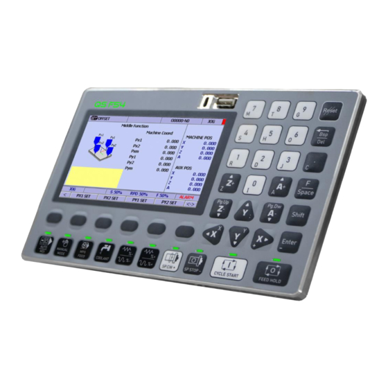
Summary of Contents for QT QS F54
-
Page 2: Table Of Contents
F54 OPERATION MANUAL INDEX OVERVIEW ...................................... 3 FUNCTION SCREEN ..................................6 MAIN SCREEN ................................6 OVERVIEW OF FUNCTIONS ............................. 7 COORDINATE SCREEN .............................. 9 2.3.1 INSTRUCTION TO DIVIDE SELECTED AXIS OF RELATIVE COORDINATE BY 2 ........... 10 PROGRAM SCREEN ..............................13 2.4.1 PROGRAM SCREEN 1 ............................. -
Page 3: Overview
F54 OPERATION MANUAL 1 OVERVIEW FUNCTION KEYS TABLE FUNCTION NAME OF KEYS Enter letters, numberable. Note: o To enter letters, use key combination Shift + The key have letter below Reset System Backspace, delete character Use to enter F letter, When combine with Shift key will create blank space. - Page 4 F54 OPERATION MANUAL Confirm Cycle Start: Start machining Feed Hold: Pause machine Move A axis direction to (+) and (-) Use this key to scroll page down Move X axis direction to (+) and (-) Move Y axis direction to (+) and (-) Use these keys to move curso up/down, left/right in function screen.
- Page 5 F54 OPERATION MANUAL Use to Enable / Disable the spindle. Combine with Shift key to Increase / Decrease the speed of the spindle. www.qstcnc.com...
-
Page 6: Function Screen
F54 OPERATION MANUAL 2 FUNCTION SCREEN 2.1 MAIN SCREEN EXPLAINING TABLE DESCRIPTION Name of window Name of working program Working mode Warning light ( Red / Green ) ABS Coordinate DIS Coordinate Operating parameter Alarm box Go to next page Function keys Go to previous page Working mode &... -
Page 7: Overview Of Functions
F54 OPERATION MANUAL 2.2 OVERVIEW OF FUNCTIONS FUNCTION Coordinate: Switch Half Coordinate Zero Zero All Program Execute Open File o Select / De-select o Select All / De-select All o Copy o Delete Offset Work Set o Apply Machine o Apply AUS o INC Input o Middle Function Tool Set... - Page 8 F54 OPERATION MANUAL o ON/OFF NC cut Maintain Alarm Warning History Alarm History Warning Back up Diagnostic NC Bit NC Reg Macro Debug Parameter General Axis Spindle Hardware User Macro Option 1 System Bit o PREV System Reg o C(16) o C(32) Find Revious Find Next...
-
Page 9: Coordinate Screen
F54 OPERATION MANUAL 2.3 COORDINATE SCREEN Manipulate: From the main screen, press F1 button to select COORD. www.qstcnc.com... -
Page 10: Instruction To Divide Selected Axis Of Relative Coordinate By 2
F54 OPERATION MANUAL Explain: Support user to monitor & interact with the coordinates of machine. EXPLAINING TABLE DESCRIPTION Switch to another coordinate Divide (REL POS) by 2 Move selected axis back to zero (REL POS) Move all axis back to zero (REL POS) Note: - REL POS: Relative Position 2.3.1 INSTRUCTION TO DIVIDE SELECTED AXIS OF... - Page 11 F54 OPERATION MANUAL Step 2: - Select Half www.qstcnc.com...
- Page 12 F54 OPERATION MANUAL Step 3: - Select the axis that you want to devide by 2, example here is Y axis. Step 4: - Check the coordinate after divided. Note: - Do the same for Zero & Zero All axis of REL POS. www.qstcnc.com...
-
Page 13: Program Screen
F54 OPERATION MANUAL 2.4 PROGRAM SCREEN Manipulate: - From the main screen, select F2 to open PROGRAM screen. 2.4.1 PROGRAM SCREEN 1 www.qstcnc.com... - Page 14 F54 OPERATION MANUAL Explain: - Support user can draft, edit working program EXPLAINING TABLE DESCRIPTION Working program Size of program % of working value o S: Speed of spindle o RPD: Rapid speed o F: Feedrate speed Execute Execute working program Open File Access to system memory Manipulate: - Press arrow button to go to next PROGRAM page.
-
Page 15: Program Screen 2
F54 OPERATION MANUAL 2.4.2 PROGRAM SCREEN 2 EXPLAINING TABLE DESCRIPTION Go to line Move to indication command line Search Searching for object Replace Replace object with another object Delete line Delete command line 2.4.3 PROGRAM SCREEN 3 www.qstcnc.com... -
Page 16: Access To System Memory
F54 OPERATION MANUAL EXPLAINING TABLE DESCRIPTION Copy from Copy object at present position Copy to Copy object to another place Paste Paste object to selected place 2.4.4 ACCESS TO SYSTEM MEMORY Manipulate: - From Program screen, press F3 to access to system memory. - Page 17 F54 OPERATION MANUAL EXPLAINING TABLE DESCRIPTION System memory USB drive Delete File / Folder Select / Deselect 1 object Select All / Deselect All object Open File / Folder Copy file / folder www.qstcnc.com...
-
Page 18: Offset Screen
F54 OPERATION MANUAL 2.5 OFFSET SCREEN Manipulate: - From the main screen, press F3 key to select OFFSET. www.qstcnc.com... -
Page 19: Workset Function Screen
F54 OPERATION MANUAL Explain: - Support user to adjust working value or position of workpiece. EXPLAINING TABLE DESCRIPTION Offset coordinate of workpiece Enter value box Access to Work Set function to establish the center coordinate of workpiece Access to Tool Set function to establish the values such as: Height, Diameter of cutting tool. - Page 20 F54 OPERATION MANUAL Explain: - This function will support user to assign the coordinate of machine or of center point of workpiece such as: External Shift, MGP Shift, G54(G54P1), G55(G54P2), … EXPLAINING TABLE DESCRIPTION Assign the coordinate of machine (MACHINE POS) Assign the coordinate of center point ( AUX POS ) Increase the present value Access to middle function...
- Page 21 F54 OPERATION MANUAL Step 2: - Enter the value that you want to increase & press to confirm. www.qstcnc.com...
- Page 22 F54 OPERATION MANUAL Step 3: - Check the value after added • ASSIGN THE COORDINATE OF MACHINE (MACHINE POS) Step 1: Select the coordinate that you want to assign the value by using the arrow key to scroll page up /down.
- Page 23 F54 OPERATION MANUAL Step 2: - Select the axis that you want to assign the coordinate, example here is X axis. - Select Work Set function. www.qstcnc.com...
- Page 24 F54 OPERATION MANUAL Step 3: - Select APPLY MACH. www.qstcnc.com...
- Page 25 F54 OPERATION MANUAL Step 4: - Select Selected Axis Step 5: - Check the value after assigned coordinate of machine (MACHINE POS). Note: Do the same steps to assign the coordinate ( AUX POS ) www.qstcnc.com...
- Page 26 F54 OPERATION MANUAL • INCREASE THE PRESENT VALUE BY ENTER VALUE. Step 1: - Select the coordinate that you want to increase value, example here is G54 (G54P1). Step 2: - Enter the value that you want to increase and select INC INPUT.
-
Page 27: Middle Function
F54 OPERATION MANUAL Step 3: Check the value after added. 2.5.2 MIDDLE FUNCTION Explain: - This function support user can quickly get the center point of workpiece. 4 point for square, rectangle workpiece, 3 point for circle workpiece. Manipulate: - From OFFSET screen, select MIDDLE FUNC. www.qstcnc.com... - Page 28 F54 OPERATION MANUAL Get center point by 4 points ( Px1,Px2,Py1,Py2 ) EXPLAINING TABLE DESCRIPTION The coordinates of edge correspond to the position of the image. The coordinates of center point after calculated www.qstcnc.com...
- Page 29 F54 OPERATION MANUAL INSTRUCTION STEPS Step 1: - Move the tool head to reach to the edge of workpiece follow the position on the depiction image. Then setting up the value to ( PX1, PX2, PY1, PY2 ). Step 2: - After you finish setting up these points ( PX1, PX2, PY1, PY2 ), the coordinate of center point will be calculated and display by (Pxm, Pym).
- Page 30 F54 OPERATION MANUAL Get center point by 3 points P1(Px1, Py1) , P2(Px2,Py2), P3(Px3,Py3) Step 1: - Move the tool head to reach to the edge of workpiece follow the position on the depiction image. Then setting up the value to ( P1, P2, PY3 ). Step 2: - After you finish setting up these point (P1,P2,P3).
-
Page 31: Tool Set Screen
F54 OPERATION MANUAL Step 3 - The coordinate of center point after calculated, it will be displayed by (Pxm,Pym) 2.6 TOOL SET SCREEN Explain: - Support user can establish the working value of cutting tool such as: Height, Diameter. Beside that you can assign the coordinate of machine www.qstcnc.com... -
Page 32: Tool No Screen
F54 OPERATION MANUAL (MACHINE POS) or (AUX POS) by select APPLY MACH or APLLY AUX. EXPLAINING TABLE DESCRIPTION DIA.(D) diameter of cutting tool LEN.(H) height of cutting tool GEO. Geometry offset value of cutting tool WEAR. là thông số bu độ mòn của dao cắt Assign the coordinate of machine (MACHINE POS) Assign the coordinate of center point (AUX POS) Increase the present value... -
Page 33: Monitor Screen
F54 OPERATION MANUAL 2.7 MONITOR SCREEN Explain: - Help user can monitor working parameters, coordinate of machine and access these function: Program, Simulator, MDI, Auto Option. EXPLAINING TABLE DESCRIPTION All Coordinates of machine Program is being used Monitoring table while machining o SA( Spindle Act ): real speed of spindle while machining (rpm/min) o FA( Feedrate Act ): reall cutting speed... -
Page 34: Simulator Screen
F54 OPERATION MANUAL o FP ( Feedrate Program ): cutting speed on program (mm/min) o L: command line is running o H: Number of height offset o D: Number of diamter offset o T ( Tool No ) : Name of tool is having in spindle o CYC ( Cycle ) : number of cycle completions... - Page 35 F54 OPERATION MANUAL EXPLAINING TABLE DESCRIPTION Simulation shape of working program Establish the position of workpiece Auto scale the shape to fit to screen frame Select simulation type ( Engraving 2D, Milling 2D, Engraving 3D, Milling 3D ) Display the informations of program after simulated (Xmin, Xmax, Ymin, Ymax, Zmin, Zmax) www.qstcnc.com...
-
Page 36: Mdi
F54 OPERATION MANUAL 2.9 MDI Explain: - Support user to create the program. Thao tác: - Select to switch to manual data input mode EXPLAINING TABLE: DESCRIPTION Program is off after switch to MDI Access to Simulation Open MDI window Access to AUTO OPTION screen www.qstcnc.com... -
Page 37: Auto Option Screen
F54 OPERATION MANUAL Note: - To enter letters (Look at FUNCTION KEYS TABLE). - Select CLEAR to delete current program. 2.10 AUTO OPTION SCREEN www.qstcnc.com... -
Page 38: Mainten Screen
F54 OPERATION MANUAL Explain : - Support user can playback at any command line or re-machining at the line that stopped before when the machine has the probem , replace tool, suddenly power off. EXPLAINING TABLE DESCRIPTION Last line Display the number of command line that stopped before. -
Page 39: Diagnos Screen
F54 OPERATION MANUAL Explain: - Support User to check & review the error, alarm annouce of machine. Manipulate: - Use key ( F1,F2,F3,F4) to select function EXPLAINING TABLE DESCRIPTION Review alarm announce Review warning announce Review alarm history Review warning history 2.12 DIAGNOS SCREEN Explain: - Allow user to access &... -
Page 40: Macro Debug Screen
F54 OPERATION MANUAL EXPLAINING TABLE DESCRIPTION Access to table of system bit Access to table of system registers Access to table of variables of Macro program 2.12.1 MACRO DEBUG SCREEN Manipulate: - From DIAGNOS screen, press F3 to select MACRO DEBUG. - Page 41 F54 OPERATION MANUAL www.qstcnc.com...
-
Page 42: Parameter Screen
F54 OPERATION MANUAL EXPLAINING TABLE DESCRIPTION TERMINAL: is a content display window of macro program. LOCAL VAR: Local variables GLOBAL VAR: Global variables 2.13 PARAMETER SCREEN Explain: - User access to this function to check, monitor all parameters of machine such as: Parameter of axis, Spindle, Hardware of controller, …... - Page 43 F54 OPERATION MANUAL EXPLAINING TABLE MÔ TẢ Truy cập vào bảng tham số người dùng thiết lập Truy cập vào bảng tham số chương trinh Macro Truy cập vào tham số các công giao tiếp Truy cập vào trang tham số tùy chọn www.qstcnc.com...
-
Page 44: Plc Ladder Screen
F54 OPERATION MANUAL 2.14 PLC LADDER SCREEN Explain: - Support user to monitor working status & interact with PLC Ladder. EXPLAINING TABLE DESCRIPTION Searching box Comment box Access to table of system bit of PLC Access to table of system register of PLC Searching device before Searching next device www.qstcnc.com... -
Page 45: Sys Bit Screen
F54 OPERATION MANUAL 2.14.1 SYS BIT SCREEN Explain: - Display data bit of PLC. Thao tác: - Use arrow key to switch to another bit.. - Press to move to previous page. EXPLAINING TABLE DATA BIT DESCRIPTION Input Bit Output Bit Timer PLC Bit Counter PLC Bit Memory PLC Bit... -
Page 46: Sys Reg Screen
F54 OPERATION MANUAL 2.14.2 SYS REG SCREEN Explain: - Display value on register of PLC. Manipulate: - Use F1,F2,F3,F4 keys to move between data bit of register. EXPLAINING TABLE REGISTER DESCRIPTION Timer C(16) Counter 16 bit C(32) Counter 32 bit Register Memory PLC www.qstcnc.com... -
Page 47: System Screen
F54 OPERATION MANUAL 2.15 SYSTEM SCREEN Explain: - Allow user to access to system functions such as: Import/Export PLC program, Macro, change data of HMI, establish system parameter :Date-Time, HMI mode, …. www.qstcnc.com... -
Page 48: Access To System Functions
F54 OPERATION MANUAL EXPLAINING TABLE DESCRIPTION Version of software Information of hardware QR code of QS Technology website 2.15.1 ACCESS TO SYSTEM FUNCTIONS Step 1: - From main screen, select SYSTEM box. www.qstcnc.com... - Page 49 F54 OPERATION MANUAL Step 2: - Select LOGIN box Step 3: - Enter user password “ 1415 “ & select OK. www.qstcnc.com...
-
Page 50: Plc Program Import Controller
F54 OPERATION MANUAL TABLE OF SYSTEM FUNCTION FUNCTION DESCRIPTION Import/Export: o Parameter / Offset o PLC DATA I/O o Macro o HMI FIRMWARE Firmware update / backup o Time / Date o Network SYS.INT o Memory o Option 2.15.2 PLC PROGRAM IMPORT CONTROLLER Step 1: - After entered the user password, plug in USB drive to controller and select DATA I/O box. - Page 51 F54 OPERATION MANUAL Step 2: - Select PLC DATA box Step 3: - Select IMPORT www.qstcnc.com...
- Page 52 F54 OPERATION MANUAL Step 4: - Select the data to import and select confirm. Note: - Do the same steps to Import/Export data for Macro program, Parameter, HMI data , … www.qstcnc.com...
-
Page 53: Firmware Update
F54 OPERATION MANUAL 2.15.3 FIRMWARE UPDATE Step 1: - From SYSTEM screen, select FIRMWARE box. Step 2: - Select Update www.qstcnc.com... - Page 54 F54 OPERATION MANUAL Step 3: - Select the folder that have firmware file then select CONFIRM box to start update process. www.qstcnc.com...
-
Page 55: Establish Date - Time
F54 OPERATION MANUAL 2.15.4 ESTABLISH DATE – TIME Step 1: - Form SYSTEM screen, select SYS.INT box. Step 2: - Select Time/Date www.qstcnc.com... - Page 56 F54 OPERATION MANUAL Step 3: - Establish time values then select SET TIME box. www.qstcnc.com...
Need help?
Do you have a question about the QS F54 and is the answer not in the manual?
Questions and answers