Table of Contents
Advertisement
Quick Links
Advertisement
Table of Contents

Related Manuals for Dante Inovonics Broadcast 541


Summary of Contents for Dante Inovonics Broadcast 541
-
Page 5: Table Of Contents
TABLE OF CONTENTS Section I – INTRODUCTION 541 PRODUCT DESCRIPTION Introduction ....................5 Product Features ..................5 541 TECHNICAL SPECIFICATIONS Specifications.................... 6 Block Diagram ................... 7 Section II – INSTALLATION GENERAL Unpacking and Inspection ................ 8 MOUNTING, POWER AND ENVIRONMENT Rack Requirement.................. - Page 6 Section IV – USING THE WEB INTERFACE Internal Webserver .................. 15 The Menu List ..................16 Menu Variances ..................16 ‘Responsive’ Webpages ................. 16 THE WEBPAGE HEADER Monitor ID ....................16 Station ID ....................16 Total-Mod Display ................... 16 Presets ....................16 Remote Listening ..................
- Page 7 Incoming Internet Access ............... 42 ® DANTE AND AoIP STREAMING IP Settings ....................43 The AoIP MAC Address ................43 Link Speed....................43 AES67 Enable ..................43 Audio Format ..................43 Transmit Flows..................44 The Dante Controller ................44 — 3 —...
- Page 8 SNMP OPERATION Overview ....................44 Mode ......................44 Security ....................44 Ports ......................45 Trap Destinations ..................45 The MIB File ..................... 45 EMAIL AND SMS/TEXT MESSAGING Email and Text Notifications..............45 SMTP Setup ..................... 45 Recipients (Send To)................46 Notifications (Send What) ...............
-
Page 9: 541 Product Description
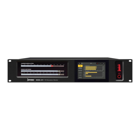
Section I INTRODUCTION 541 PRODUCT DESCRIPTION The 541 is Inovonics’ fourth-generation FM Modulation Monitor. Introduction It delivers a wealth of information about the transmitted signal in terms of the RF carrier and all subcarriers, the audio compo- nent defining the technical quality that the listener hears, and full decoding of RDS data and SCA audio. -
Page 10: Specifications
48kHz sample rate; 110 transformer- laboratory-grade test equipment. coupled. Dante/AES67 Compatible AoIP Port: (RJ45) RF & RECEPTION Output at 44.1kHz (Dante-only) or Tuning Range: Tunes 76.0MHz-108.0MHz in 44.1kHz/48kHz (Dante/AES67); AoIP utility 100kHz steps. -
Page 11: Block Diagram
POWER, ENVIRONMENTAL, MISCELLANEOUS Operating Environment: 32°F/0°C - 122°F/50°C; 0%-95% non-condensing relative humidity; Power Requirement: 10,000ft/3048m. 88-264VAC, Single-Phase; 12W. Size and Weight: AC Mains Power Factor: 3.5”H x 19”W x 9”D; 12 lbs. shipping weight. Better than 0.6/0.9* Conformances: *Upon customer request EN50081-1 / EN50082-1 93/68/EEC 2002/95/EC... -
Page 12: Section Ii - Installation
Section II INSTALLATION GENERAL This section of the manual addresses the physical installation of the 541 at its operating location, the ‘nuts and bolts’ of connect- ing the unit. This section also references pages where pertinent setup options and adjustments are discussed. As soon as the equipment is received, inspect carefully for any Unpacking and shipping damage. -
Page 13: Ac Mains Power
The 541 employs an internal ‘universal’ switchmode power sup- AC Mains ply that accommodates mains voltages between 88V Power 264V Certified self-protection circuits have replaced the once-familiar fuseholder. If you need to replace the North-American mains plug with an- other, you will find that the individual cord conductors are color- coded in one of two ways. -
Page 14: Aes Digital Line Output
Dante/AoIP streaming first requires basic Dante setup under the Webpage or LCD Dante menus as detailed on Pages 43-44. Output levels are adjusted on the Setup / MPX and Audio Outputs / Dante Output Webpage, or under the LCD Setup / Dante Outputs menu. -
Page 15: Section Iii - Preparing To Connect
Section III PREPARING TO CONNECT THE 541 FRONT PANEL Setup and operating adjustments of the 541 are under firmware Front Panel vs. control; there are no jumpers, switches or mechanical potenti- Web Interface ometers. The unit may be set-up locally through the front-panel Setup LCD-touchscreen, or remotely using the built-in Webserver inter- face and any networked computer, tablet or mobile device with... -
Page 16: The Admin Menu
Arrows in the illustration identify items in the LCD screen header. An additional icon will pop up in the header when an alarm is triggered, just to the left of the headphone symbol. Touch that icon to show the alarm panel screen. Arrow #1 points to the Menu-select tab. -
Page 17: Led Level Readout Bars
finger to push the slider left and right or click the < and > but- tons to fine-tune your setting. Similarly, for the LCD display itself, Brightness: controls the back- light. Timeout: sets the time that the display will remain on after you finger leaves the screen. -
Page 18: Connecting
DHCP is the factory-de- fault network Mode:. The IP Address: of your 541 ap- pears in the first box. DHCP should work for you at least initially, but if your 541 needs a static IP address, touch Static IP to unlock grayed-out boxes underneath. -
Page 19: Section Iv - Using The Web Interface
Section IV USING THE WEB INTERFACE The Inovonics 541 internal Webserver contains multiple interac- Internal tive pages, or menus, for setup and operation of your unit. These Webserver pages provide ready and interactive access to all settings, readouts, graphics, audio monitoring and alarms. Now Playing is the landing, ‘home’... -
Page 20: The Menu List
A list of all the Webpage menus can be found at the left edge of The Menu List any page. Click on any menu heading to go immediately to that Webpage. We have made every effort to coordinate the Webpages with the Menu LCD-touchscreen menus, but this is not possible in all cases. -
Page 21: Remote Listening
Click the loudspeaker icon at the top-right of this or Remote any other Webpage to listen to off-air audio through Listening your Web browser. Up to 10 listeners can access this audio stream simultaneously, but listeners may also be restricted. Instructions for FM or SCA program selection and for limiting the number of listeners are given in the streaming audio discussion on Page 40. -
Page 22: The Alarm Panel
SNR, or signal-to-noise in percent relative to an ideal (100%) sig- nal; and signal Multipath distortion, again relative to an ‘ideal’ value of 0.0%. Carrier Offset does not display with absolute, com- pliance-level accuracy, but is useful to show shorter-term ‘wan- derings’... -
Page 23: Rf Input Selection
The 541 has rear-panel connectors labeled ANTENNA and HIGH RF Input LEVEL RF INPUT. The high-level BNC input is generally used Selection when a wired direct connection to the transmitter is preferred over off-air signal reception. Under RF Input: select Antenna or High Level. This selection does become a part of the saved Preset Stations data and would allow automatic ‘pushbutton’... -
Page 24: Station Presets
pass function following the SCA demodulator. Use these con- trols to clean up the audio as best you can. Deviation (kHz): defines the 100%-modulation point of the SCA subcarrier. The default value of ±5kHz is the de-facto specifica- tion, although FM subcarrier parameters are no longer subject to government regulation in the US. -
Page 25: Fm Carrier Modulation
Finally, you must program the Rotation Time (Sec):, and this may take some planning. Many of the 541 alarms have Time On (Sec): and Time Off (Sec): settings that will impact your Rotation Time (Sec): choice. See the Alarms discussion beginning on Page 34. The Status: display gives a second-by-second countdown of rota- tion time or shows that the feature is Off. -
Page 26: Pilot, 38Khz And Rds Levels
With an appropriate filter selected (Page 19), these modulation readings should not be affected by accompanying HD Radio pro- grams. Precise IF filtering eliminates false indications of FM- overmod at any HD carrier-pair injection ratio. Any observed in- teraction between analog and digital program channels should certainly prompt further investigation. -
Page 27: Demodulated Fm Audio
calculated and integrated within a floating 1-minute measure- ment window. As a point of reference, 0dBr equates to the r.m.s. power of a single-tone sinewave modulated with a peak deviation of ±19kHz, which is some 12dB below the ±75kHz FM peak devia- tion limit. -
Page 28: Fm Program Loudness
XTalk (stereo crosstalk) is similar to the Sep (stereo separation) measurement, but in this case it indicates the level difference between the L+R and L-R program audio components. Like the Sep readout, it is useful only with tone tests and is not an indi- cation of crosstalk issues in the program audio. -
Page 29: Sca Subcarrier Measurements
Loudness Window: down to 30 seconds, as may be dictated by the station’s programming format. This metering method reflects the broadcast implementation of the BS.1770 Standard, and is explained in further detail in EBU Loudness Standard R-128. SCA Subcarrier Measurements The % scale shows the injection level of the SCA subcarrier in percent of total FM carrier modulation. -
Page 30: Spectrum Plots
SPECTRUM PLOTS The 541 monitor includes an advanced, high-resolution FFT- based spectrum analyzer that delivers detailed and annotated graphic displays of selected signals. Images may be viewed ei- ther through the Webpages utility or from the front-panel LCD- touchscreen. Each signal selected for viewing carries its own family of graph setup options below the display. -
Page 31: The Fm Baseband Spectrum
carrier level. Response: set to Average yields the default display shown in the example. Peak will show the peak value of the sig- nal, and Hold accumulates the highest peak value until the func- tion is deselected. At the bottom, the display Averages: the number of FFT compu- tations selected in the drop-down box. -
Page 32: History Plots
HISTORY PLOTS The 541 offers plots of reception and audio parameters viewable over a specified time period, from the past minute to a full, 24- hour time study. Although these data are available through both the Webpages and front-panel LCD-touchscreen displays, Webpage presenta- tion provides some extended options covered in this discussion that will be found missing with front-panel operation. -
Page 33: Modulation
study over a longer period you may select a window that shows up to the last 24 Hours. Rolling your mouse over this screen will drag a cursor over the plot, the arrow and vertical white line just to the right of center in the example screenshot. -
Page 34: Integrated Loudness History
This screen plots the loudness level of the FM broadcast, adher- Integrated ing to the ITU-R BS.1770 Standard discussed on Page 24. These Loudness readings are integrated (long-term) “LU” loudness measure- History ments. Per the previous dis- cussion, LU numbers don’t equate well with total carrier modula- tion peak readings, as... -
Page 35: Oscilloscope
OSCILLOSCOPE A built-in oscilloscope utility has been included for viewing au- dio and other waveforms through either the Webpages or the LCD-touchscreen displays. Vertical sensitivity is scaled and an- notated with respect to the 100%-modulation point, and the hor- izontal timebase adjusts for the most meaningful display of the selected signal. -
Page 36: The Bandscanner™ Utility
THE BANDSCANNER™ UTILITY The 541 BandScanner is an annotated RF spectrum analyzer util- ity that is able to graphically display the entire FM band. From the front panel, BandScanner is found under Graphs. 1) Band-scanning interrupts all mod-monitor functionality dur- Warnings! ing the scan cycle, as it essentially tunes across the band and collects data from each station in the market. -
Page 37: Bars And Dots
‘Hovering’ over a yellow-only bar pops up only the Freq: and Bars and Dots RSSI: in a pop-up box. At the completion of an RSSI + RDS scan, a yellow bar with a red dot indicates a station with RDS. Hover- ing over an RDS station will also present call letters and the PTY (Program TYpe) information as shown in the example. -
Page 38: Alarm Status
Clicking the Clear/Reset RDS bar at the bottom will indeed clear the registers and begin a new RDS data collection. Reset is auto- matic when the station is changed. ALARMS The 541 provides alarms for signal or program-related error con- Alarm Status ditions. -
Page 39: Overmod
Alarm: On ‘arms’ the Overmod function in this and all other alarms to be dis- cussed. If the alarm is turned Off, there will be no indicator on the Now Playing or Alarm Webpages, no contact closure at a rear-panel GPO terminal, nor will the 541 send SMS/text or Email alerts to station personnel or log the alarm. -
Page 40: Audio Loss
We’ll use Audio Loss as Audio Loss a typical example of a hysteresis-type alarm. Alarm: must of course be set On to arm this function. The grayed- out Level (dB): meter shows the current pro- gram level for the sta- tion being monitored. -
Page 41: Rds Radiotext Not Updated
To enable the PI mis- match function, enter the station’s true PI code in the PI Code: box. The code being received at the moment is shown as the Current PI:. If you are confident that what you see there is indeed the PI of your station, simply enter that same hex value and click Save. -
Page 42: Sca Loss
program appropriate Threshold (%):, Time On (Sec): and Time Off (Sec): settings. Stations running an SCA subcarrier first need to set up the SCA Loss proper measurement parameters on the Tuner menu (Page 19). Only then should this alarm be used. Current SCA Injection (%): is shown so that threshold and timing sliders may be set appropriately. -
Page 43: Radio Settings
The log holds data on Alarm, type which monitored Sta- tion it pertains to (im- portant when the Sta- tionRotation feature is active), the Time and Date received plus the alarm Duration. You may View Alarm Log on your screen and even filter the results by overtyping Filter alarms…... -
Page 44: Mpx Output
Dante/AoIP output streams on the Streams rear-panel RJ45 AoIP Port. As with other digital outputs, the Level (dBFS): may be set between –30 and 0. Other Dante settings are addressed in a separate subsection shortly. The 541 offers HTTP/Icecast Streams for general ‘tune-in’ listen-... -
Page 45: Save The Settings
Once streaming parameters have been set-up or modified, set- Save the tings must be saved by clicking the Save bar at the bottom of the Settings! section. This action will reset the streaming utility and discon- nect any current Web listeners, who then must then log back on. The rear-panel General Purpose Outputs (GPOs) serve as ‘tallies’... -
Page 46: Network Setup And Internet Access
NETWORK SETUP AND INTERNET ACCESS With Mode: set to DHCP, your router IP Setup automatically assigns the 541 an IP Address: and will populate the four as- sociated fields, although they will be ‘grayed-out’ and you’ll not be able to edit those data. -
Page 47: Dante ® And Aoip Streaming
It is generally also com- patible with proprietary systems from independent manufactur- ers of AoIP-enabled products. The Dante-based AoIP utility of the 541 is quite similar to the IP Settings product’s general networking function. Like the LAN connection, the independent AoIP connection may accept IP address assign- ments in either a DHCP or Static IP assignment Mode:. -
Page 48: Transmit Flows
Dante AoIP flows; AES67 flows are locked to PCM 24 regardless of this setting. Sample Rate: is forced to 48kHz for AES67 streaming, but 44.1kHz is the 541 default rate unless AES Enable: has been set to Enable. -
Page 49: Ports
the read/write strings on your SNMP Manager monitoring device. Do a Save after entering your text. The default SNMP Ports, SNMP Port: 161 and Trap Port: 162, are cus- Ports tomary for a majority of SNMP operations. Overtype these de- faults to change them, followed by a Save. -
Page 50: Recipients (Send To)
Next enter up to ten email recipients, typing-in the full email ad- Recipients, dress. After this you’ll decide who gets what alert. (Send To) Email addresses typically take the form of the upper example here. If instead you wish to send a text message to a recipi- ent’s cell phone, the entry may look like the second image. -
Page 51: Presentation Formats
Grab and drag the Time Zone (Hours): slider for the proper offset from Universal Coordinated Time for your location. In this example, the –8 represents West Coast US (Pacific) time. The time at the top of the page will update rap- idly, so you can simply drag the slider until the time shown here agrees with your Rolex Cosmograh, or per-... -
Page 52: Signing In
receiver or make changes to any settings. Once passwords have been assigned, click Save to lock them into nonvolatile memory. Once passwords have been entered and saved, the front-panel Now Playing screen will be the only one visible, and all Web inter- face screens will be locked out. -
Page 53: Reboot
To save a profile to your computer, under Configu- ration click: Download Hardware Profile. With the Firefox browser used in this example, Windows 10 automatically saves the file to your Windows Down- loads folder as a small file with a .json extension. From there you can move it to a location of your choice. -
Page 54: 541 Manual
A PDF of the 541 manual has been included in the firmware. 541 Manual The bottom of the Admin screen shows the Serial Number: of your ‘About’ Info 541, gives the current Firmware Rev: and displays the Uptime:, or how long your 541 has been running since power was last ap- plied. -
Page 55: Inovonics Warranty
INOVONICS WARRANTY TERMS OF SALE: Inovonics products are sold with an understanding of “full satisfaction”; that is, full credit or refund will be issued for prod- ucts sold as new if returned to the point of purchase within 30 days following their receipt, provided that they are returned complete and in an “as received”...
Need help?
Do you have a question about the Inovonics Broadcast 541 and is the answer not in the manual?
Questions and answers