
Summary of Contents for AMS Wadkin Bursgreen BGRA-350
- Page 1 Wadkin Bursgreen Industrial Arm Saw WB 400 Supplied by Advanced Machinery Services Tel: 0844 844 9949 Fax: 0844 844 4744 www.advancedmachinery.co.uk...
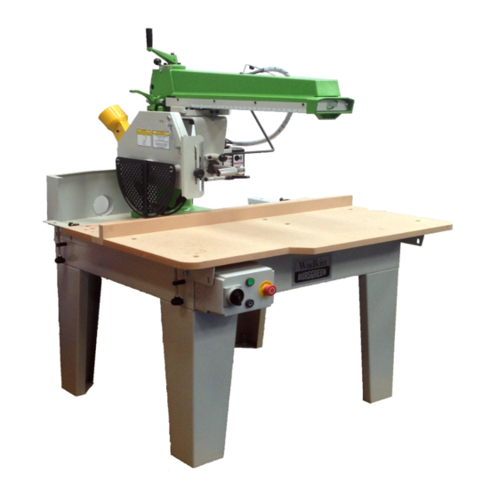
- Page 2 OPERATING INSTRUCTIONS and PARTS MANUAL RADIAL ARM SAW BGRA-350/400/450...
-
Page 3: Table Of Contents
HEALTH&SAFETY SAFETY OF WOODWORKING MACHINES Woodworking machines can be dangerous if improperly used. The wide range of work of which they are capable, requires adequate safeguarding arrangements against possible hazards. Many injuries to machinists are caused by carelessness or failure to use the guards provided or to adjust them correctly. -
Page 4: Warnings
1. Read and understand the entire owner's manual before attempting assembly or operation. 2. Read and understand the warnings posted on the machine and in this manual. Failure to comply with all of these warnings may cause serious injury. 3. Replace the warning labels if they become obscured or removed. 4. - Page 5 21. Check the saw blade for cracks or missing teeth. Do not use a cracked or dull blade or one with missing teeth or improper set. Make sure the blade is securely locked on the arbor. 22. Keep hands clear of the blade area. Do not reach past the blade to clear parts or scrap with the saw blade running.
-
Page 6: Specification
Specification Model(standard arm/longer URAS URAS URAS arm) 350/350A 400/400A 450/450A Maximum diameter of saw 350mm 400mm 450mm Maximum saw projection 108mm 133mm 155mm Crosscut capacity 90˚ 340x108mm 340x133mm 330x155mm Crosscut capacity 45˚ 290x108mm 290x133mm 290x155mm Height of work table 813mm 813mm 813mm 3 Phase... -
Page 7: Notice Of Installation
NOTICE OF INSTALLATION When installing, the machine must be leveled up by means of packing pieces under the feet. The machine table should be slightly high at the front end. This will ensure that the saw unit remains in the back position when not in use. -
Page 8: Support Bracket
Support Bracket Fix the outer support bracket (#307) by flat washer (#304), lock washer (#156) and hex cap bolt (#303). First, fix the bracket (#307) which has warning label on it on the right side of machine. Second the other bracket (#307) on the left side of machine. -
Page 9: Motor And Semi-Universal Head
Motor and Semi-Universal Head (Figure 4) Loosen the round head screws (#58), take off the plate (#45) then loosen the hex socket cap screws (#44) and remove the arm end cap (#43). Insert the bearing on the motor set (#113) into the track of the arm (as the arrow direction shows), then install the arm end cap and plate back as original. -
Page 10: Notice Of Wiring
Notice of Wiring The motor and control gear have been wired in before dispatch. All that is required is to connect the power supply to the starter. Important notice when connecting to power supply: 1. Check the voltage, phase and frequency correspond to those on the motor plate, also the correct coils and heaters are fitted to the starter. -
Page 11: Spring Balancer
Spring Balancer Figure 9 shows how spring balancer and motor set connected together. Pull the ball of the spring balancer (#56) to the motor set and fix it by screw (#204). Adjust tensile force by turning knob (#55). Turn counterclockwise for tighten the force;... -
Page 12: Wood Table & Dust Chute
WOOD TABLE (Figure 10) Place wood table (#316, Fig. 10) then #314, #313, #315. Fix the wood tables by flat head socket screw (#318), washer (#304), lock washer (#156) and nut (#106). DUST CHUTE (Figure 11) Dust chute is installed on the back side of machine by screw (#53), washer (#51) and lock washer (#52). -
Page 13: Saw Blade Angle Adjustment
SAW BLADE ANGLE ADJUSTMENT Saw Blade and Table (Figure 12 & 12-1) Lower the saw blade to touch the table surface slightly. Place a 90˚ square on the table and check that the blade is at a 90˚ angle to the table. If the angle is not accurate, adjust the knob (#193, Fig. -
Page 14: Saw Blade & Fence
Saw Blade and Fence (Figure 13, 13-1 and 13-2) Pull the saw blade close to the fence, then place the square as Fig 13 shown. If there is a gap between saw blade and square, adjust knob (#319). Adjust knobs (#319) on the left and right of machine to make it no gap between the square and the saw blade. -
Page 15: Saw Blade Angle Adjustment
SAW BLADE ANGLE ADJUSTMENT The saw blade can do 90˚ to 45˚ tilting. To change the angle of the saw blade: loosen the lock handle (#157), hold the pull handle (#147) then pull the round knob (#152), the motor/saw blade can be moved to your required angle. (Fig. -
Page 16: Swing Arm & Column Rise And Fall Adjustment
SWING ARM & COLUMN RISE AND FALL ADJUSTMENT (Figure 16) Loosen the nylon nut (#16), turn the rise & fall handle (#25) to the height you need, and then tighten the nylon nut (#16). Make sure that the lock handle (#157) and nylon nut (#16) are fastening securely before operation. - Page 18 Swing Arm Assembly Index Part Description Size Qty. 001……… 16500001………….. Base………………………………. ……………... …..1 002……… 914M123403……… Flat Washer……………………… ø12………… …..4 003……… 904M12060……….. Hex Cap Bolt…………………….. M12×60…… …..9 004……… 915M12000……….. Lock Washer…………………….. ø12………… …..4 005……… 910M12000……….. Hex Nut………………………….. M12………... …..4 006……… 917M05045……….. Lock Pin…………………………. ø5×45……… …..2 007………...
- Page 19 Swing Arm Assembly Index Part Description Size Qty. 037……… 912M12000………….. Nylon Nut………………………... M12…………... …..2 038……… 16500016…………….. Location Bolt……………………. ………………... …..3 039……… 908M10010A………... Set Screw………………………… M10×10……… …..4 040……… 15500017…………….. Slide Rod………………………… ………………... …..2 ………….. 16500017…………….. Slide Rod………………………… ………………... …..2 041……… 915M05000………….. Lock Washer…………………….. M5……………. …20 042………...
- Page 21 Semi-universal Head Assembly Index Part Description Size Qty. 101……… 16500023…………….. Roller Bracket…………………... ………………... …..1 102……… 16500024…………….. Plain Roller Pin…………………. ………………... …..1 103……… 16500025…………….. Eccentric Roller Pin……………. ………………... …..3 104……… 16500026…………….. Concave Bearing………………... ………………... …..4 105……… 912M10000………….. Nylon Nut……………………….. M10…………... …..4 106………...
- Page 22 Semi-universal Head Assembly Index Part Description Size Qty. 158……… S1060009……………. Emergency Stop Switch………… ………………... …..1 159……… 9145162302…………. Flat Washer……………………... 5/16”…… …… …..3 160……… 930PG9000………….. Cable Gland……………………... PG9…………... …..4 161……… L1650001……………. Power Cord (Main Switch) ……. ………………... …..1 163……… 16500063……………. Locating Latch Hook…………… ………………... …..1 164………...
- Page 24 Blade Guard Assembly Index Part Description Size Qty. 118……… M1650001…………… Motor…………………………6HP3PH400V50HZ …..1 119……… 16500031…………….. Arbor Flange……………………. ………………... …..1 120……… 9181010010………….. Key……………………………….. 10×10………… …..1 121……… 954016000…………… Saw Blade……………………….. Option……….. …..1 122……… 16500032…………….. Saw Flange(Front) ……………... ………………... …..1 123……… 910M20000………….. Hex Nut………………………….. M20…………... …..1 124………...
- Page 25 Blade Guard Assembly Index Part Description Size Qty. 174……… 16500054…………….. Screw…………………………….. M6×25……….. …..1 175……… 16500055…………….. Rubber Ring…………………….. ………………... …..1 176……… 910M06000L………... Hex Nut………………………….. M6……………. …..4 177……… 93800015…………….. Handle…………………………… ………………... …..1 178……… 915316000…………… Lock Washer…………………….. 3/16” ………… …..2 179……… 906316012…………… Round Head Screw……………... 3/16” ×1/2” ….. …..2 180………...
- Page 27 Base and Table Assembly Index Part Description Size Qty. 301……… 15500071……………… Base……………………………... ……………….. …..1 ………….. 16500071……………… Base……………………………... ……………….. …..1 302……… 16500072…………….. Leg For Base…………………… ……………….. …..4 303……… 904M10020…………… Hex Cap Bolt…………………… M10×20……… …18 Ø 304……… 914M102803…………. Flat Washer……………………. 10…………… …34 305………...
Need help?
Do you have a question about the Wadkin Bursgreen BGRA-350 and is the answer not in the manual?
Questions and answers