Table of Contents
Advertisement
Quick Links
SMA 2000 D Operating Manual V3.0A
Revision Date: 2009-11-15
HIGH LEVEL AND TANK OVERFILL ALARM SYSTEM
Magnetic Float Reed Switch Type
OPERATING MANUAL
MODEL: SMA 2000D
November 2009
PROPRIETATRY RIGHTS NOTICE
The information contained in this manual is the property of Scanjet Macron Co Ltd
And must not be used/copied/transmitted to third party without the express written authority of Scanjet Macron Co.,Ltd.
Advertisement
Table of Contents

Subscribe to Our Youtube Channel
Summary of Contents for Scanjet SMA 2000D
- Page 1 OPERATING MANUAL MODEL: SMA 2000D November 2009 PROPRIETATRY RIGHTS NOTICE The information contained in this manual is the property of Scanjet Macron Co Ltd And must not be used/copied/transmitted to third party without the express written authority of Scanjet Macron Co.,Ltd.
-
Page 2: Table Of Contents
SMA 2000 D Operating Manual V3.0A Contents 1. Introduction ......................................3 1.1 General Description ..................................3 1.3 Factory tests ....................................5 2 Installation Description ..................................5 2.1 Electrical Parts ..................................... 5 2.2 Electrical installation on the system ............................6 2.3 Float Level Switches ..................................7 3 Technical Description ................................... -
Page 3: Introduction
1.1 General Description SCANJET MACRON SMA-2000 series is ready to be supplied as a complete system, i.e. either as a single or a dual point system. The system is uniquely developed in order to cope with the latest high environmental requirements from USCG, IMO and classification societies. - Page 4 SMA 2000 D Operating Manual V3.0A 2. Main Components of the system The system consists of following equipments. Electric Cabinet This cabinet must be located in CCR as safe area, and alarm panel, all electrical components such as I.S repeater, power supply and relays are mounted inside cabinet.
-
Page 5: Factory Tests
SMA 2000 D Operating Manual V3.0A 1.3 Factory tests The system is completely assembled, calibrated and tested at the factory. All internal wiring is ready finished. The inspection report with certificate number is included. The check sheet and FAT report will be attached in final documentation. -
Page 6: Electrical Installation On The System
SMA 2000 D Operating Manual V3.0A 2.2 Electrical installation on the system MOUNTING PLATE IN CABINET OVERFILL LEVEL HIGH LEVEL PWR ON PWR ON P WR ON P WR ON PWR ON PWR ON PWR ON PWR ON PWR ON PWR ON PWR ON PWR ON... -
Page 7: Float Level Switches
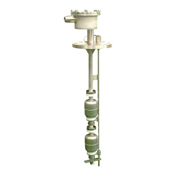
SMA 2000 D Operating Manual V3.0A 2.3 Float Level Switches The following description for level switches installation should be observed carefully. Storage preparations The system must be protected against corrosion and external damage if it will be stored for a long time before installation Installation ... -
Page 8: Technical Description
SMA 2000 D Operating Manual V3.0A 3 Technical Description 3.1 Magnetic Float Level Switch The level switch is equipped with one or two floats, with built-in permanent magnets in each float. Float Actions Alarm Condition Reed Switch Digital Multi-tester Float shift upwards 98% or 95% alarm De-activated, open... - Page 9 SMA 2000 D Operating Manual V3.0A D1030D dual channel type has two independent input channels and actuates the corresponding output relay. Two actuation modes can be independently DIP switch configured on each input channel: NO In/NE relay or NO In/ND relay. Code D1030D Name...
- Page 10 SMA 2000 D Operating Manual V3.0A Function: 1 or 2 channels I.S. switch repeater for contact or EN60947-5-6 Proximity Provides 3 port isolation. (Input/output/supply) Signalling LEDs: Power supply indication (green), Output status (yellow), Line fault (red). Field Configurability: NO/NC input for Contact/Proximitor, NE/ND relay operation and Fault detection enable/disable. EMC: Fully compliant with CE marking applicable requirements Front Panel and Features:...
-
Page 11: Alarm Display Unit
SMA 2000 D Operating Manual V3.0A 3.3 Alarm Display Unit 1 FND: Tank name will be shown when new alarms occur 2, 3 Alarm LEDs: Overfill 98% is RED color and High 95% is Yellow 4 Alarm LED for Power failure 5, 6, 7, 8, 9 Buttons and Buzzer "Buzzer Stop", "Accept/Reset", "Alarm Hold", "Lamp/Function Test"... - Page 12 SMA 2000 D Operating Manual V3.0A ⑥ Push button, RED Color for "Buzzer Stop" and "Accept/Reset" Sound stop and Alarm accept/reset ⑦ Push button Lock type, Green Color for "Alarm Hold" Normally, this function can be used at sea going mode by pressing “Alarm Hold” button. If the function is already activated prior to cargo loading, it must be de-activated and green lamp should be off.
-
Page 13: Operating
SMA 2000 D Operating Manual V3.0A 4 Operating Before starting the system The following installation for the system should be checked. Make sure that earth wire and screen (shield) are isolated from the ground properly in the level switch connection box. Make sure that Main power supply and backup power supply are connected to correct power source according to electrical cabling diagram. -
Page 14: Fault Finding
SMA 2000 D Operating Manual V3.0A 5 Fault Finding 5.1 Power Failure Alarm Alarm will be activated if either main 230 VAC or 24 VDC backup power supply is missing. Alarm will be de- activated after supply power is restored. 5.2 Alarm Malfunction In case the tank alarm LED with buzzer is activated on alarm display unit even though tank is empty or similar case. -
Page 15: Maintenance And Replacement Of Defective Parts
SMA 2000 D Operating Manual V3.0A 6. Maintenance and Replacement of Defective Parts 6.1 Magnetic Float The replacement procedure is carried out as following numbers: 5. Remove screw for upper float replacement 4. Float 3. Seat ring: It is linked with test device rod 2. -
Page 16: Printed Circuit Board
SMA 2000 D Operating Manual V3.0A 6.5 Printed Circuit Board 3. PCB support bar 1. Terminal Block 2. Protection Plate 6. Aluminum Plate for Tank names 5. FND and Alarm LED Board 4. Micro-com. CPU Board 1. Terminal Block 1. FND 2. -
Page 17: User Programming For Alarm Display Unit
SMA 2000 D Operating Manual V3.0A 7 User Programming for Alarm Display Unit 7.1 General Description The PCB of Alarm Display Unit is set up at the factory to suit different applications. Alarm settings can be adjusted by programming switches onboard. The switches for changing of factory setting values are easily accessible without any need to disconnect cable gland materials at the back side of PCB. -
Page 18: Programming Chart
SMA 2000 D Operating Manual V3.0A 7.3 Programming Chart In order to access programming after start-up, the MODE key should be pressed as below. Para. 1 S4 SET S3 DOWN S1 MODE CH-16 CH-16 CH-15 S5 EXIT Exit program S3 DOWN S2 UP CH-00 CH-14... -
Page 19: Appendix
SMA 2000 D Operating Manual V3.0A <Information>: There are three external alarm relay groups on PCB. Group 0: For COT Horn and Light handling, Terminal number: 40A1B Group 1: For HFO tank Horn and Light handling, Terminal number: 41A1B Group 2: For Pump room bilge well Horn and Light handling, Terminal number: 42A1B If the setting is CH12-0 in this parameter, the external relay group 0 will take care of alarm channel 12.
Need help?
Do you have a question about the SMA 2000D and is the answer not in the manual?
Questions and answers