
Subscribe to Our Youtube Channel
Related Manuals for ICOP Technology EB-EHL Series

Summary of Contents for ICOP Technology EB-EHL Series
- Page 1 User’s Manual EB-EHL Intel® Elkhart Lake Processor Embedded Barebone & Compact BOX PC EB-EHL-J6-8G EB-EHL-J6-16G EB-EHL-J6-32G (Revision 1.0A) EB-EHL User’s Manual IUMEB-EHL-01 Ver.1.0A Aug, 2023...
- Page 2 REVISION DATE VERSION DESCRIPTION 2023/8/4 Version 1.0A New Release EB-EHL User’s Manual IUMEB-EHL-01 Ver.1.0A Aug, 2023...
- Page 3 Global: www.icop.com.tw USA: www.icoptech.com Japan: www.icop.co.jp Europe: www.icoptech.eu China: www.icop.com.cn For technical support or drivers download, please visit our websites at: https://www.icop.com.tw/resource_entrance This Manual is for the EB-EHL series. EB-EHL User’s Manual IUMEB-EHL-01 Ver.1.0A Aug, 2023...
- Page 4 SAFETY INFORMATION Read these Safety instructions carefully. Please carry the unit with both hands, handle carefully. Make sure the voltage of the power source is correct before connecting the equipment to the power outlet. Do not expose your BOX PC to rain or moisture in order to prevent shock and fire hazard.
-
Page 5: Table Of Contents
Content Content ........................... iv Ch. 1 General Information ....................1 1.1 Product Description ....................2 1.2 Product Specifications .................... 3 1.3 Product Dimensions ....................5 1.4 Mounting Instruction ....................6 1.5 Ordering Information ....................7 Ch. 2 System Installation ....................9 2.1 CPU Board Outline .................... -
Page 6: 1 General Information
General Information 1.1 Product Description 1.2 Product Specifications 1.3 Product Dimensions 1.4 Mounting Instruction 1.5 Ordering Information EB-EHL User’s Manual IUMEB-EHL-01 Ver.1.0A Aug, 2023... -
Page 7: Product Description
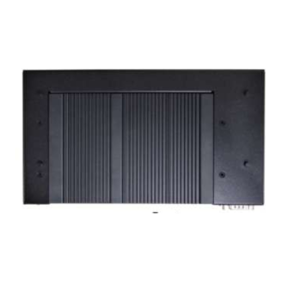
1.1 Product Description ICOP Technology Inc. is proudly going to release a brand new BOX PC, which offers fanless design, high performance and low power consumption. The EB-EHL is powered by Intel® Elkhart Lake J6412 processors, and up to 32GB of SO-DIMM DDR4 module that handles processing more efficiently and provides faster performance. -
Page 8: Product Specifications
1.2 Product Specifications CPU BOARD SPECIFICATIONS Intel® Elkhart Lake J6412 (Quad core) Cache L2: 1.5MB Cache BIOS AMI BIOS Memory 8GB / 16GB / 32GB DDR4 Intel® HD Graphics: HDMI x2 (Max. 4096x2160@60Hz) Display Dual Channel LVDS x1 (Max. 1920x1080@60Hz) eDP x1 (Max. - Page 9 MECHANICAL & ENVIRONMENT +12~24 VDC Power Adatper Only Power Requirement (DC JACK 5.5x2.5mm plug support) Power Adapter +12VDC@ 3.34A (40W) Operating Temperature 0~+60°C Storage Temperature -30~+70°C Operating Humidity 0% ~ 90% Relative Humidity, Non-Condensing Dimensions 245x126x37.2mm (9.65"x4.96"x1.46") Weight 1.12 Kg Certificates CE / UKCA / FCC / VCCI EB-EHL User’s Manual...
-
Page 10: Product Dimensions
1.3 Product Dimensions EB-EHL User’s Manual IUMEB-EHL-01 Ver.1.0A Aug, 2023... -
Page 11: Mounting Instruction
1.4 Mounting Instruction EB-EHL series reserve 4 mounting holes as below figure. Please use M3*4 screws to lock the EB-EHL system upon the chassis if want. EB-EHL User’s Manual IUMEB-EHL-01 Ver.1.0A Aug, 2023... -
Page 12: Ordering Information
1.5 Ordering Information Product Code CPU Series CPU Type 1. Product Code:Code 1~2. EB:Embedded Barebone & BOX PC Series. 2. CPU Serial:Code 3~5。 EHL: Intel® Elkhart Lake Series. 3. CPU Type:Code 6~7。 J6: Intel Elkhart Lake J6412.(Standard; Quad Core 10W) 4. - Page 13 PART NUMBER DESCRIPTION Embedded Barebone & BOX PC w/Intel Elkhart Lake EB-EHL-J6-8G J6412/8GB DRAM /6U/2*2.5GbE LAN/2S Embedded Barebone & BOX PC w/Intel Elkhart Lake EB-EHL-J6-16G J6412/16GB DRAM /6U/2*2.5GbE LAN/2S EB-EHL-J6-32G Embedded Barebone & BOX PC w/Intel Elkhart Lake J6412/32GB DRAM /6U/2*2.5GbE LAN/2S AC –...
-
Page 14: 2 System Installation
System Installation 2.1 CPU Board Outline 2.2 Connector Summary 2.3 Connector Pin Assignments 2.4 External I/O Overview 2.5 External I/O Pin Assignment EB-EHL User’s Manual IUMEB-EHL-01 Ver.1.0A Aug, 2023... -
Page 15: Cpu Board Outline
2.1 CPU Board Outline EB-EHL CPU Board EB-EHL User’s Manual IUMEB-EHL-01 Ver.1.0A Aug, 2023... -
Page 16: Connector Summary
2.2 Connector Summary Connector Type of Connections Pin # DDR4 SO-DIMM Slot External SO-DIMM Slot 260-pin Power DC Jack External Power DC Jack Connector 2-pin 2 * USB3.1 (Gen. 2) External Dual USB3.1 Connector 18-pin 2* USB3.0 External Dual USB2.0 Connector 10-pin 2 * HDMI External Dual HDMI Connector... -
Page 17: Connector Pin Assignments
LVDS 2.3 Connector Pin Pin # Signal Name Pin # Signal Name Assignments LVDSB_D3- LVDSB_D3+ LVDSB_CLK- LVDSB_CLK+ LVDSB_D2- LVDSB_D2+ Power DC Jack LVDSB_D1- LVDSB_D1+ Pin # Signal Name LVDSB_D0- LVDSB_D0+ +12~24V Power Adapter Input NC/DDC_DAT NC/DDC_CLK COM1 (RS232/422/485) LVDSA_D3+ LVDSA_D3- Pin # Signal Name Pin #... - Page 18 JPBL Pin # Signal Name Pin # Signal Name EDP_LANE3- EDP_LANE3+ EDP_LANE2- JPCLR EDP_LANE2+ EDP_LCD_HPD EDP_LANE1- EDP_LANE1+ /EDP_DET Pin # Signal Name EDP_LANE0- PNL0_BLEN 1-2 Open (Default) Normal EDP_LANE0+ PNL0_BLCTL 1-2 Closed Clear RTC EDP_SDA 3-4 Open (Default) Normal EDP_AUXP EDP_SCL 3-4 Closed Clear CMOS...
-
Page 19: External I/O Overview
2.4 External I/O Overview NOTE: COM1 RS232/422/485 is selected by BIOS setting. Please refer the section, 4.3 to set the function in the BIOS setup. EB-EHL User’s Manual IUMEB-EHL-01 Ver.1.0A Aug, 2023... -
Page 20: External I/O Pin Assignment
External Assignment DC Jack (+12~24Vdc Power Adpter Input) HDMI Pin # Signal Name Pin # Signal Name TMDS_Data2+ +12~24Vdc Power Input TMDS_Data2_Shield TMDS_Data2- COM1 (RS232/422/485) TMDS_Data1+ (Change mode by BIOS Setup) TMDS_Data1_Shield Signal Signal TMDS_Data1- Pin # Pin # Name Name TMDS_Data0+ DCD1... - Page 21 USB 3.1 Pin # Signal Name SSRX- SSRX+ SSTX- SSTX+ EB-EHL User’s Manual IUMEB-EHL-01 Ver.1.0A Aug, 2023...
-
Page 22: 3 Hardware Installation
Hardware Installation EB-EHL supports various kinds of storages for industrial application, divided into M.2 2242 SATA (M-Key) and 2.5” SATAIII HDD/SSD. 3.1 Installing the M.2 2242/2280 Storage 3.2 Installing the M.2 B-Key (3024) and M.2 M-Key (2230) Modules 3.3 Installing the Micro SIM Card (Must have 3G/4G of M.2 B-Key (3024) Module in advance) 3.4 Installing the LVDS and backlight cables for external LCD panel EB-EHL User’s Manual... -
Page 23: Installing The M.2 M-Key (2242/2280) Storage
3.1 Installing the M.2 M-key (2242/2280) Storage EB-EHL series support M.2 M-key (2242/2280) PCIe Gen. 3 *2 / SATA interface NVME. Please refer the below instructions. [STEP] Remove the 9 screws of bottom side as the image below. Pull up the rear cover. - Page 24 For 2242 or 2280 storage, please use a M2 screw driver to remove the top screw in advance, and then use M4 screw driver to move the bottom screw to the correct position. (For example, The below figures show moving the screw for M.2 2242 storage.) Plug the M.2 storage in the slot and lock it up.
-
Page 25: Installing The M.2 B-Key (3024) And M.2 E-Key (2230) Modules
3.2 Installing the M.2 B-Key (3024) and M.2 E-Key (2230) Modules EB-EHL series support M.2 B-key (3024) USB3.1/USB2.0 interface and M.2 E-key (2230) USB2.0/PCIe Gen3 *1 interface. Please refer the below instructions. [STEP] Remove the 9 screws of bottom side as the image below. - Page 26 Remove the screw and plug the M.2 B-Key (3024) and M.2 E-Key (2230) modules on the slots, and then lock them up. Take the rear cover back and lock 9 screws. EB-EHL User’s Manual IUMEB-EHL-01 Ver.1.0A Aug, 2023...
-
Page 27: Installing The Micro Sim Card (Must Have 3G/4G Of M.2 B-Key (3024) Module In Advance)
3.3 Installing the Micro SIM Card (Must have 3G/4G of M.2 B-key (3024) Module in advance) EB-EHL series support Micro SIM Card for 3G/4G of M.2 B-key (3024) USB3.1/USB2.0 module [STEP] Please refer the section, 3.2 to install 3G/4G of M.2 B-key (3024) Module in advance. -
Page 28: Installing Lvds And Led Backlight Cables For External Lcd Panel
3.4 Installing LVDS and LED backlight cables for external LCD panel EB-EHL series has reserved one hole to through the LVDS and LED backlight cables for external LCD panel. [STEP] Remove the 9 screws of bottom side as the image below. - Page 29 Set the LED backlight Voltage. Push out and remove the small cover. EB-EHL User’s Manual IUMEB-EHL-01 Ver.1.0A Aug, 2023...
- Page 30 Through the cables to the rear cover and put the cover back. Lock 9 screws back. Please refer the section 4.6 to setup the LCD display settings. EB-EHL User’s Manual IUMEB-EHL-01 Ver.1.0A Aug, 2023...
-
Page 31: 4 Drivers And Bios Instruction
Drivers and BIOS Instruction 4.1 Operating System Support and Drivers 4.2 BIOS Hot Key 4.3 BIOS COM1 Setting (RS232/RS422/RS485) 4.4 BIOS COM2 Setting (Change Settings) 4.5 BIOS AT Mode Setting (Support Auto-Power On Function) 4.6 BIOS LCD Display Settings (by LVDS Signals) 4.7 BIOS Serial Port Console Redirection 4.8 BIOS Load Default Setting EB-EHL User’s Manual... -
Page 32: Operating System Support And Drivers
4.1 Operating System Support and Drivers The EB-EHL provides the Win10 and Win11 drivers. Please get the drivers from ICOP technical support URL: https://www.icop.com.tw/resource_entrance For Linux, most Linux distributions support Intel® Elkhart Lake Processor and user can install Linux upon EB-EHL directly. Please contact your region sales for technical support if you have any question. -
Page 33: Bios Hot Key
4.2 BIOS Hot Key After power on, it supports BIOS hot key as below. Press < Del > to enter the AMI BIOS setup Press < F7 > to enter Popup Menu EB-EHL User’s Manual IUMEB-EHL-01 Ver.1.0A Aug, 2023... -
Page 34: Bios Com1 Setting (Rs232/422/485)
4.3 BIOS COM1 Setting (RS232/422/485) COM1 can be set to be RS232/422/485 function. Please refer the instruction as below. (1) Press “Del” key into the BIOS setup, and go to “Advanced” and “Super IO Configuration”. (2) Go to “Serial Port 1 Configuration”. EB-EHL User’s Manual IUMEB-EHL-01 Ver.1.0A Aug, 2023... - Page 35 (3) Go to Transmission Mode and set RS232/422/485 function. (4) After setting, please press “F4” key to save & exit. EB-EHL User’s Manual IUMEB-EHL-01 Ver.1.0A Aug, 2023...
-
Page 36: Bios Com2 Setting (Change Settings)
4.4 BIOS COM2 Setting (Change Settings) COM2 can be changed settings as below. (1) Press “Del” key into the BIOS setup, and go to “Advanced” and “Super IO Configuration”. (2) Go to “Serial Port 2 Configuration”. EB-EHL User’s Manual IUMEB-EHL-01 Ver.1.0A Aug, 2023... - Page 37 (3) Go to “Change Settings” and set IO address and IRQ if you want. (4) After setting, please press “F4” key to save & exit. EB-EHL User’s Manual IUMEB-EHL-01 Ver.1.0A Aug, 2023...
-
Page 38: Bios At Mode Setting (Support Auto-Power On Function)
4.5 BIOS AT Mode Setting (Support Auto-Power On Function) EB-EHL supports “Auto-Power On function”, user doesn’t need to press “power button” for system power on and just needs to plug power source input and system will be power on automatically. (1) Press “Del”... - Page 39 (3) After setting, please press “F4” key to save & exit. Note: After system shut down by operating system, EB-EHL will be power-off. For next booting up, user just needs to re-plug power adapter or power reset again, while system will be boot-up automatically. EB-EHL User’s Manual IUMEB-EHL-01 Ver.1.0A Aug, 2023...
-
Page 40: Bios Lcd Display Settings (By Lvsd Signals)
4.6 BIOS LCD Display Settings (by LVSD Signals) EB-EHL supports external LCD display by LVDS signals output. Please refer the LCD display settings as below. (1) Press “Del” key into the BIOS setup and go to “Chipset” and “System Agent (SA) Configuration”. - Page 41 (3) Set “LVDS Panel Type” you want. (4) Press “F4” key to save configuration and reset. EB-EHL User’s Manual IUMEB-EHL-01 Ver.1.0A Aug, 2023...
-
Page 42: Bios Serial Port Console Redirection
4.7 BIOS Serial Port Console Redirection EB-EHL supports Serial Port Console Redirection as below. (1) Press “Del” key into the BIOS setup and go to “Advanced” and “Serial Port Console Redirection”. (3) Set “Console Redirection” to be “Enabled”. EB-EHL User’s Manual IUMEB-EHL-01 Ver.1.0A Aug, 2023... - Page 43 (4) Go to “Console Redirection Settings”. (5) Set “Terminal Type” to “VT100+”. Emulation: [ANSI]: Extended ASCII char set; [VT100]: ASCII char set; [VT100+]: Extended VT100 to support color, function keys, etc.; [VT-UTF8]: Uses UTF8 encoding to map Unicode chars onto 1 or more Bytes.
-
Page 44: Bios Load Default Setting
(4) After setting, please press “F4” key to save & exit. 4.8 BIOS Load Default Setting (1) Press “Del” key into the BIOS setup, and press “F3” key to load optimized defaults. EB-EHL User’s Manual IUMEB-EHL-01 Ver.1.0A Aug, 2023... - Page 45 (2) After setting, please press “F4” key to save & exit. EB-EHL User’s Manual IUMEB-EHL-01 Ver.1.0A Aug, 2023...
-
Page 46: Warranty
Merchandise Authorization (RMA) number. Returned goods should always be accompanied by a clear problem description. All Trademarks appearing in this manuscript are registered trademark of their respective owners. All Specifications are subject to change without notice. © ICOP Technology Inc. 2023 EB-EHL User’s Manual IUMEB-EHL-01 Ver.1.0A Aug, 2023...
Need help?
Do you have a question about the EB-EHL Series and is the answer not in the manual?
Questions and answers