Table of Contents
Advertisement
Quick Links
Advertisement
Table of Contents

Subscribe to Our Youtube Channel
Related Manuals for parr 6790

Summary of Contents for parr 6790
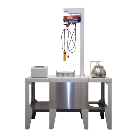
- Page 1 6790 Detonation Calorimeter Operating Instruction Manual...
-
Page 2: Table Of Contents
TABLE OF CONTENTS PREFACE Scope Related Instructions Explanation of Symbols Safety Information Intended Usage Cleaning & Maintenance General Specifications Environmental Conditions Provisions for Lifting and Carrying Unpack Carefully INSTALLATION Environmental Conditions Required Utilities & Power Requirements Power Connection Motor Connection Thermistor Probe Installation Electrical Hookup of 6772 Calorimetric Thermometer Dynamic Pressure Recorder Connections... -
Page 3: Preface
6790 Detonation Calorimeter PREFACE Scope Explanation of Symbols This manual contains instructions for installing and On Position operating the Detonation Calorimeter. Off Position To assure successful installation and operation, the user must study all instructions carefully before start- ing to use the calorimeter to obtain an understanding... -
Page 4: Cleaning & Maintenance
Hoist supplied with the calorimeter. Please refer to 230V 1.0 Amps 50/60 Hz the electric hoist operating instructions supplied before use. Combustion Vessel Hoist for 6790 110V 60 Hz Unpack Carefully 230V 50 Hz Unpack the equipment carefully and check all the parts against the packing list. -
Page 5: Installation
1.0 Amps 50/60 Hz parts for the thermometer. However, should replace- ment of the entire thermometer become necessary, Combustion Vessel Hoist for 6790 it will need to incorporate the special internal wiring. 110V 60 Hz Refer to the data label affixed to back panel of the... -
Page 6: Electrical Hookup Of 6772 Calorimetric Thermometer
INSTALLATION (Continued) Dynamic Pressure Recorder Connections Data Acquisition Hardware The pressure transducer connects to the input of the CAUTION! The 24 V power supply Piezotron coupler via the white coaxial cable. Keep should not be connected to the wall outlet the electrical connection at the transducer covered during installation or maintenance/repair. -
Page 7: Data Acquisition Software
6790 Detonation Calorimeter INSTALLATION (Continued) Data Acquisition Software Use Test this device option in NI Device Monitor and confirm that the connected device is properly NOTE: in order to use NI DAQExpress software, enumerated as device 1 [Dev1]. Change the desig- the user needs to set up an account with ni.com. -
Page 8: Operating Instructions
OPERATING INSTRUCTIONS Determination Correction (K) Parameters: The Detonation Calorimeter has been developed to test high explosives. It is based upon the design 0.00026 first built at Lawrence Radiation Laboratories and described by D.L. Ornellas in the provided paper. 0.00011 The first of design was produced for Nammo Talley Inc. -
Page 9: Safety For Detonation Calorimeters
6790 Detonation Calorimeter OPERATING INSTRUCTIONS (Continued) 4. Place the head on the cylinder using the hoist if Within the vessel the sample is burned in an oxygen necessary. environment usually limited to 40 bar (580 psi) or less. The rapid combustion of the sample in this 5. -
Page 10: Recording The Pressure
OPERATING INSTRUCTIONS (Continued) Safety for Detonation Calorimeters (Cont.) Recording the Pressure 5. The calorimeter measures the total energy Double click the Pressure.task file located in the release of combustion or detonation within DAQExpress folder on the distribution CD. the vessel. A maximum energy release is set into the control system, should this limit be Simply click “Record”... -
Page 11: Parts Lists & Drawings
6790 Detonation Calorimeter PARTS LISTS & DRAWINGS A500A Vessel Parts List Spare Parts - Parts List PART NO. DESCRIPTION PART NO. DESCRIPTION 560A CYLINDER, T316 (6790) 45C10 FUSE WIRE NI ALLOY 10CM 565A HEAD, A286 (6790) 96AC ELECTRODE INSULATOR 552A O-RING BUNA 2-350 4.600 IDX.210... -
Page 12: A500A Vessel Drawing: Closure Details
PARTS LISTS & DRAWINGS (Continued) A500A Vessel Drawing: Closure Details 555A 552A 1/2-13 X 1-1/4 HHCS O-RING (2-350) TYP (12) PLACES 565A HEAD 560A CYLINDER A500A Vessel Drawing: Cross Section Guide 60° 15° 30° 60° NOTE: SECTION VIEWS A-A, B-B, AND C-C SHOW THE ARRANGEMENT FOR CALIBRATION, AS IT LEAVES SEE PAGE15 FOR THE ARRANGEMENT WHEN APPARATUS IS IN... -
Page 13: A500A Vessel Drawing: Cross Section A-A & Gland Detail
6790 Detonation Calorimeter PARTS LISTS & DRAWINGS (Continued) A500A Vessel Drawing: Cross Section A-A & Gland Detail SEE DETAIL D ELECTRODE (2) SW09FT #3 WASHERS (2) SN0856HX 2-56 HEX NUTS 556A (2) 558A PUSH NUT NUT, 10-32 TIGHTEN TO 5-6 FT/LBS... -
Page 14: A500A Vessel Drawing: Cross Section B-B & Valve Detail
PARTS LISTS & DRAWINGS (Continued) A500A Vessel Drawing: Cross Section B-B & Valve Detail SEE DETAIL E 1.25 562A INLET TUBE A445A SUPPORT ASSY SA1932RD06 10-32 x 3/8 RHMS 446A FUEL CAPSULE SC1332SC02 (2) 463A 6-32 X 1/8 SHSS NEEDLE PLUGS TO BE INSTALLED FLUSH WITH TOP OF 344A2 APPLY (LOCKTITE OR EQUIV) -
Page 15: A500A Vessel Drawing: Setup For End User Installation
6790 Detonation Calorimeter PARTS LISTS & DRAWINGS (Continued) A500A Vessel Drawing: Setup for End User Installation (2) 558A NUT, 10-32 (2) SA1932RD04 10-32 X 1/4 RHMS SECTION A-A 564A SACRIFICAL HEAD PLATE SB3724SC08 3/8-24 X 1/2 SHCS 563A SACRIFICAL CYLINDER PLATE... -
Page 16: Support Stand Parts List
SUPPORT ROD ALUM (12.99" REF) FOR REFERENCE ONLY 3384HC SUPPORT RING ALUM 3412HC WORK SURFACE HDPE A1268DD STR MOTOR ASSY,12V A1470DD STIRRER HUB ASSY (6790) A1475DD AIR CAN ASSY (6790) A1485DD BUCKET ASSY (6790) A1574HC2 LIFT TUBE ASSY (6790) A2610HC17 FLOORSTAND (6790) 90.37... -
Page 17: Support Stand Drawing: Top & Front View
6790 Detonation Calorimeter PARTS LISTS & DRAWINGS (Continued) Support Stand Drawing: Top & Front View 62.38 (2) 799DD BUSHINGS 3427HC MTG BRKT, HOIST. RH (2) SB2520HX12 1/4-20 X 3/4 HHCS (2) SN2520HX 1/4-20 HEX JAM NUT (2) SW25FT WASHER 24.00 3426HC MTG BRKT, HOIST. -
Page 18: Calorimeter In Stand Drawing: Cutaway View
PARTS LISTS & DRAWINGS (Continued) Calorimeter in Stand Drawing: Cutaway View 538VB MALE CONN, NYLON (REF) 1600DD TAPE, HI-TEMP AL FOIL (SEE NOTE 5) 1417E2 THERMISTOR (REF) A2142E EXTENSION CABLE THERMISTOR (2) SW16FT WASHER, #8 (REF) PARTIAL DETAIL VIEW (2) 1260HCF SCREW 8-32 X 1/2 (REF) SECTION A-A 1486DD SPACER (REF) (3) WE2520FT12 SCREW, NYLON(REF) -
Page 19: 1824 Oxygen Filling Connection Drawing: Exploded View
6790 Detonation Calorimeter PARTS LISTS & DRAWINGS (Continued) 1824 Oxygen Filling Connection Drawing: Exploded View NOTES: ALL PIPE THREADS TO BE SEALED WITH PTFE TAPE = ASSEMBLY ORDER 1824 Oxygen Filling Connection Parts List PART NO. DESCRIPTION 4VB3 PACKING GASKET...
Need help?
Do you have a question about the 6790 and is the answer not in the manual?
Questions and answers