Table of Contents
Advertisement
Quick Links
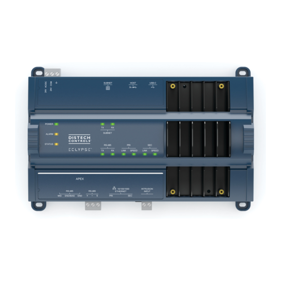
ECLYPSE APEX
Product Description
The ECLYPSE APEX is a powerful IoT Edge controller that offers enhanced performance and dedicated spaces to IoT and AI developers. It facilitates
HVAC system maintenance, increases efficiency of equipment and optimizes energy consumption by leveraging the latest available technology on site.
General Installation Requirements
For proper installation and subsequent operation of each controller, pay special attention to the following recommendations:
£
Upon unpacking the product, inspect the contents of the carton for shipping damages. Do not install damaged modules.
£
Avoid areas where corroding, deteriorating or explosive vapors, fumes or gases may be present.
£
Ensure the mounting surface can support the controller, DIN rail, and any user-supplied enclosure.
£
Allow for proper clearance around the controller's enclosure, wiring terminals, and HOA switches to provide easy access for hardware configuration
and maintenance, and to ventilate heat generated by the controller.
£
The controller's mounting orientation must be horizontal with the controller's back attached to a vertical wall surface. Orient the controller with the
ventilation slots and power supply input terminal block connectors towards the top to permit proper heat dissipation. When installed in an enclosure,
select one that provides sufficient surface area to dissipate the heat generated by the controller and by any other devices installed in the enclosure.
A metal enclosure is preferred. If necessary, provide active cooling for the enclosure.
£
The controller's Specsheet specifies the power consumption (amount of heat generated), the operating temperature range, and other environmental
conditions the controller is designed to operate under.
£
Ensure that all equipment is installed according to local, regional, and national regulations.
£
If the controller is used and/or installed in a manner not specified by Distech Controls, the functionality and the protection provided by the controller
may be impaired.
£
SELV (Separated Extra Low Voltage) inputs/outputs must be connected to other SELV equipment inputs/outputs.
£
It is recommended that the controller(s) be kept at room temperature for at least 24 hours before installation to allow any condensation that may
have accumulated due to low temperature during shipping/storage to evaporate.
£
Do not drop the controller or subject it to physical shock.
Any type of modification to any Distech Controls product will void the product's warranty.
Take reasonable precautions to prevent electrostatic discharges to the controller when installing, servicing or
operating the controller. Discharge accumulated static electricity by touching one's hand to a well-grounded
object before working with the controller.
I n s t a l l a t i o n G u i d e
Advertisement
Table of Contents

Summary of Contents for ECLYPSE APEX
- Page 1 Product Description The ECLYPSE APEX is a powerful IoT Edge controller that offers enhanced performance and dedicated spaces to IoT and AI developers. It facilitates HVAC system maintenance, increases efficiency of equipment and optimizes energy consumption by leveraging the latest available technology on site.
-
Page 2: General Wiring Recommendations
For example, keep power, hazardous voltage, SELV, PELV, network, and input wiring separate from each other. £ APEX power wiring: When connecting one wire to a controller’s terminal block clamping cage (pole), the wire must be between 18 and 14 gauge (0.82 and 2.1mm cross-sectional area). - Page 3 Do not connect the universal inputs, analog/digital outputs or common terminals to earth or chassis ground (unless stated otherwise). £ Keep input and output wiring in conduits, trays or close to the building frame if possible. APEX Dimensions Figure 2: ECLYPSE APEX dimensions 3 / 27...
-
Page 4: Power Supply Dimensions
Power Supply Dimensions The ECLYPSE APEX does not require an external power supply, however, the ECY-PS24 or ECY-PS100-240 module may be required if surpassing the limits of the APEX's integrated power supply. For recommendations according to specific applications, refer to the Product Selection Tool available in Builder: https://builder.distech-controls.com. - Page 5 IO Module Enclosure Dimensions The ECLYPSE APEX supports up to 20 IO Modules. Available IO modules come in the following dimensions. Narrow models: ECY-8UI, ECY-16DI, ECY-6UO, ECY-6UO-HOA, ECY-4UI4UO, ECY-4UI4UO-HOA, ECY-8UI6UO, ECY-8UI6UO-HOA, ECY-8UI6DOT, and ECY-8UI6DOT-HOA Wide models: ECY‑8DOR and ECY‑8DOR‑HOA. 3.20" 81.17 2.31"...
- Page 6 2.31 [58.56] 3.20 [81.17] Inter-Connection Gap: 0.01 [0.40] 0.51 [12.90] 0.83 [21.08] 4.74 [120.31] 3.18 [80.82] 5.30 [134.65] 0.73 [18.54] Back Profile Front 0.06 [1.44] Inches [Millimeters] 2.95 [74.99] Figure 7: RS-485 Communication Module 3.20 [81.17] 2.31 [58.56] Inter-Connection Gap: 0.01 [0.40] 0.51 [12.90] 0.83 [21.08] M-Bus...
- Page 7 EOL, DIP Switch, and Jumper Identification and Configuration ECLYPSE APEX The ECLYPSE APEX has an integrated end-of-line (EOL) switch and reset button located at the bottom of the controller as shown in the figure below. END/BIAS RESET Figure 9: APEX EOL switch and reset button locations...
-
Page 8: Mounting Instructions
Applies to IO Module Models DIP Switch Posi- Input / Output Option Configuration Available Signal Type Options tion Type ECY-8UI, ECY-4UI4UO, ECY-4UI4UO-HOA, UI Input option configuration Contact, Counter, 0 to 10VDC, 0 to ECY-8UI6UO, ECY-8UI6UO-HOA, 5VDC, Resistance, Thermistor ECY-8UI6DOT, and ECY-8UI6DOT-HOA ECY-8UI, ECY-6UO, ECY-6UO-HOA,... -
Page 9: Mounting Positions
IO Module Assembly Order IO Modules are connected in a left to right order, starting with the ECLYPSE APEX. When an ECY-RS485 is used, install it immediately to the right of the ECLYPSE APEX before any input/output module. This is followed by any mix of up to 20 input/output modules, including ECY Power Supplies as needed to power the input/output modules. -
Page 10: Wall-Mounted Installation
Modules should be mounted on a wall one module at a time. The first module of the assembly to be mounted should be the ECLYPSE APEX controller. Once the APEX has been attached to the wall, connect the next module on the right so that the side connectors are firmly coupled and the modules are aligned straight. - Page 11 Figure 17: For non-ECY IO modules: Separate the front and back base by gently pulling the front assembly off the back base, thereby separating the electrical connectors between the two halves. Figure 18: For ECY IO modules: Separate the front and back base by opening and pulling the hinged gull-wing covers, thereby sepa- rating the electrical connectors between the two halves.
- Page 12 Each APEX power supply can supply a maximum of 18.8W@18.8V to loads connected to the right of it, up to the next connected power supply, with cur- rent limit of 27.3W including the subnet. To calculate the number of Input/Output Extension Modules that can operate with each power supply, the num- ber of power supplies required, and their location, see the Product Selection Tool available in Builder: https://builder.distech-controls.com.
- Page 13 Max. Fast Max. Fast Acting Acting Figure 21: APEX Power wiring 3-wire Power Wiring with the ECY-PS24 Voltage: 24VAC/DC; ± 15%, Class 2 For terminal block connector wiring best practices, see General Wiring Recommendations. This is a Class 2 Product. Use a Class 2 transformer only (rated between 60 and 100VA at 24VAC) for each ECY‑PS24 power supply.
- Page 14 Figure 22: ECY-PS24 Power wiring 14 / 27...
- Page 15 Power Wiring with the ECY-PS100-240 Voltage 100-240 VAC; +10%/-15%; 50/60 Hz Overvoltage Category II - 2.5 kV For terminal block connector wiring best practices, see General Wiring Recommendations. Always conform to the wiring regulations in effect in your jurisdiction. Each ECY-PS100-240 power supply can supply a maximum of 40W to loads connected to the right of it, up to the next connected power supply. To cal- culate the number of Input/Output Extension Modules that can operate with each power supply, the number of power supplies required, and their loca- tion, see the Product Selection Tool available in Builder: https://builder.distech-controls.com.
-
Page 16: Input And Output Overview
Input and Output Overview Each ECY IO module has a number of physical connections for inputs and/or outputs. These inputs and outputs are labelled on the ECY IO modules ac- cording to the tables below. Input and output options must be configured properly in EC-gfxProgram to ensure correct input readings and output values. The controller's license may have separate limits that reduce the availability of certain options. -
Page 17: Input Wiring
Input Wiring Input options must be properly configured in EC- gfx Program to ensure correct input readings. The table below shows the ECY IO modules’ input desig- nation for each IO model. For terminal block connector wiring best practices, see General Wiring Recommendations [pg. 2]. -
Page 18: Output Wiring
Sensor Input Type ECY IO modules’ Input Connection Diagram Input Designation £ £ Voltage input used with a 3-wire 0 to 10VDC or 0 to 5VDC sensor pow- ered by an external 24 AC/DC power supply. 0-10V To Analog-To- Common Sensor Digital Converter 24VAC... -
Page 19: Communications Wiring
IP addressing, radio path planning (when the ECLYPSE Wi-Fi Adapter is connected to the con- troller), etc. It can be downloaded from our website. For optimal performance, use Distech Controls category 5e network cable or refer to the ECLYPSE User Guide for cable specifications. -
Page 20: Wireless Connection
There are two methods to connect to the controller: wired (Ethernet connection) or wireless (when the ECLYPSE Wi-Fi Adapter is connected to the con- troller). Wired Connection Network connections can be daisy-chained. CAT 5e Network Cable RJ-45 Connector To Next IP... - Page 21 Using the Controller’s Wi-Fi IP Address This procedure requires the installation of the ECLYPSE Wi-Fi adapter to one of the USB ports on the controller so that the controller becomes a hotspot to which you can connect. See a previous section on Wireless Connection. Once you are connected, you can then log in to the controller as shown be- low: 1.
- Page 22 When connecting to an ECLYPSE Controller for the first time, you will be prompt to change the password. In Network Settings, configure the controller’s network parameters so that they are compatible with your network. See the ECLYPSE User Guide for more information about network settings and how to secure the controller.
- Page 23 First and/or last daisy-chained device: - BIAS is ENABLED - EOL are ENABLED - EOL are DISABLED ECLYPSE RS-485 END/BIAS END/BIAS -EOL ON -BIAS ON Figure 27: BACnet MS/TP Communications Wiring When inserting multiple wires into a terminal-block connector, ensure to properly twist wires together prior to insertion.
- Page 24 Connect Modbus TCP devices to the same IP subnet the controller is using. This connection can be made by connecting the Modbus TCP device to an Ethernet port on the ECLYPSE APEX with a Cat5e network cable for example (see Wired Connection). For more connection options, refer to the ECLYPSE User Guide.
-
Page 25: Using The Reset Button
M-Bus communications are made by connecting meters directly in an M-Bus port. The ECLYPSE APEX integrates one M-Bus port when equipped with one ECY-MBUS extension module. The M-Bus port must be configured in EC- gfx Program prior to use. M-Bus meters are integrated into EC- gfx Program using the M-Bus device block. -
Page 26: North American Emissions Compliance
Hot-swappable ECY IO Modules ECY IO module front assemblies are hot-swappable for easy maintenance (see Input and Output Overview). The front assembly of ECY IO modules separate from the base by pushing the two latches up to unlock a module’s front assembly and then opening and pulling the hinged gull-wing covers (see Mounting Instructions). -
Page 27: Complementary Information
Distech Controls for maintenance or repair. Specifications subject to change without notice. ECLYPSE, Distech Controls, the Distech Controls logo, EC-Net, Allure, and Allure UNITOUCH are trademarks of Distech Controls Inc. BACnet is a registered trademark of ASHRAE; BTL is a registered ®...
Need help?
Do you have a question about the APEX and is the answer not in the manual?
Questions and answers