Table of Contents
Advertisement
Quick Links
P4M-440G User Manual > Introduction
Introduction
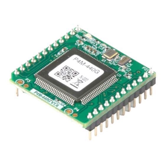
The P4M-440G is a module type of PHPoC product. Since PHPoC function is provided in module
form, it is possible to implement the board suitable for user application.
P4M-440G provides various interfaces, including 10/100M Ethernet, UART, SPI, I2C, digital
input/output, and more, making it possible to produce a wide range of products tailored to user
requirements.
※ Notice: P4M-440G is a programmable module, but this feature is initially disabled. Please refer to
the instructions of
Activating PHPoC Engine
before use.
2023-10-04
Sollae Systems
page 1 of 20
Advertisement
Table of Contents

Related Manuals for Sollae Systems P4M-440G


Summary of Contents for Sollae Systems P4M-440G
- Page 1 P4M-440G User Manual > Introduction Introduction The P4M-440G is a module type of PHPoC product. Since PHPoC function is provided in module form, it is possible to implement the board suitable for user application. P4M-440G provides various interfaces, including 10/100M Ethernet, UART, SPI, I2C, digital input/output, and more, making it possible to produce a wide range of products tailored to user requirements.
- Page 2 P4M-440G User Manual > Features Features Modular PHPoC Provides self-development PHPoC Interpreter Provides simple development environment via USB Provides 10/100Mbit Ethernet Provides 10 digital I/O ports Provides 2 UART ports Provides I2C and SPI interfaces Embeds 32.768KHz crystal for RTC...
- Page 3 P4M-440G User Manual > H/W Specification H/W Specification Input DC 3.3V (±0.16V) Power Current Consumption Typical - about 95mA Dimension 26mm x 26mm x 9mm Weight about 4g 2 X UART Ports(UART0 ~ 1), UART Baudrate: 1,200 bps ~ 230,400 bps...
- Page 4 P4M-440G User Manual > Dimension Dimension ※ Dimensions(unit : mm) may vary according to a method of measurement. 2023-10-04 Sollae Systems page 4 of 20...
- Page 5 P4M-440G User Manual > Layout Layout P4M-440G interfaces with two 12 x 1 pin headers (P1 ~ P2). The pin spacing is 2mm. Pin# Name Description P1.1 Ground P1.2 TPTX+ In/Out Ethernet Transmit + P1.3 TPTX- In/Out Ethernet Transmit - P1.4...
- Page 6 P4M-440G User Manual > Layout Pin# Name Description P2.9 SDA(0.7) In/Out UIO 0.7 / I2C SDA P2.10 U1TX(0.10) In/Out UIO 0.10 / UART1 TX P2.11 U1RX(0.11) In/Out UIO 0.11 / UART1 RX P2.12 Ground There is an STS LED located at the top-left corner of the module. This LED blinks at a 1-second interval and operates in two different patterns depending on the product's status.
-
Page 7: Usb Device
In/Out Ethernet Receive + P1.6 TPRX- In/Out Ethernet Receive - P4M-440G provides 10/100Base-TX Ethernet Interface. Note that RJ45 connector is required to use Ethernet. Refer to a circuit diagram of the Application Circuit Diagram for the connection. USB Device Pin#... - Page 8 P4M-440G User Manual > Interface Pin# Name Description P2.3 SCK(0.1) In/Out UIO 0.1 / SPI SCK P2.4 MISO(0.2) In/Out UIO 0.2 / SPI MISO P2.5 MOSI(0.3) In/Out UIO 0.3 / SPI MOSI P2.6 U0TX(0.4) In/Out UIO 0.4 / UART0 TX P2.7...
-
Page 9: Application Circuit Diagram
P4M-440G User Manual > Application Circuit Diagram Application Circuit Diagram This is an application circuit diagram for interfaces of P4M-440G. 2023-10-04 Sollae Systems page 9 of 20... - Page 10 P4M-440G User Manual > How to Use > Software(IDE) Software (IDE) PHPoC Debugger PHPoC Debugger is a software used for developing and setting PHPoC products. You need to install this program on your PC for using PHPoC. PHPoC Debugger Download Page...
-
Page 11: Usb Connection
P4M-440G User Manual > How to Use > Connecting Connecting USB Connection Connect the USB device port of P4M-440G to PC via a USB cable. Run the PHPoC Debugger. Select connected COM PORT and press connect ( ) button. If USB is successfully connected, connect button will be inactivated and disconnect button ( ) will be activated. -
Page 12: Settings Reset
P4M-440G User Manual > How to Use > Reset Reset Settings Reset Settings Reset makes all the settings of your PHPoC products to factory default. A certificate in PHPoC is also deleted. Settings Reset Procedure Step Action Product State STS LED... -
Page 13: Web Interface
TCP 80 is used for web server and you can use the interface via web browsers. How to use web interface To use the web interface, "index.php" file should be in the file system of P4M-440G. Connect to this page by entering device IP address after connecting it to network. -
Page 14: Setting Passwords
P4M-440G User Manual > How to Use > Setting Passwords Setting Passwords If you set a password for the product, you must enter the password when connecting the product via USB or network. Please refer to the PHPoC Debugger manual page for details. - Page 15 P4M-440G User Manual > How to Use > Escaping infinite reset Escaping Infinite Reset PHPoC basically runs scripts when it boots up. Therefore, it is possible that a P4M-440G cannot be escaped from infinite reboot when script contains system command such as "reboot". Refer to the Following to solve this problem since it needs to stop the running script.
-
Page 16: Device Information
P4M-440G User Manual > Device Information Device Information Device Channel Path Note UART /mmap/uart0~1 /mmap/net0 Ethernet /mmap/tcp0~4 /mmap/udp0~4 Digital I/O /mmap/uio0 10 Pins (uio0.0 ~ 0.7, 0.10, 0.11) /mmap/st0~7 /mmap/spi0 /mmap/i2c0 /mmap/rtc0 /mmap/um0~3 /mmap/nm0 ※ Refer to the PHPoC Device Programming Guide for p40 for detailed information about using devices. -
Page 17: Evaluation Board
P4M-440G User Manual > Evaluation Board Evaluation Board This evaluation board is only can be used with P4M-440G. 1. Power This is the power input port that supplies power to the board. The input voltage is DC 5V, and the... - Page 18 2. USB Device Port for connection with PC The USB device port is to connect with PC. You can access to P4M-440G via the development tool(PHPoC Debugger) by connecting USB cable to this port. You can supply DC 5V power through this port.
- Page 19 "DIS" side or leaving it unconnected deactivates it. 6. ISP Jumper You connect +3.3V or GND to the ISP# pin of the P4M-440G using this jumper. 7. P8 P8 is connected 1:1 with all the pins on the module's P2.
-
Page 20: Reset Button
P4M-440G User Manual > Evaluation Board Color Description U0TX/4 Green ON when UIO 0.4 is LOW U0RX/5 Green ON when UIO 0.5 is LOW SCL/6 Green ON when UIO 0.6 is LOW SDA/7 Green ON when UIO 0.7 is LOW...
Need help?
Do you have a question about the P4M-440G and is the answer not in the manual?
Questions and answers