Advertisement
Quick Links
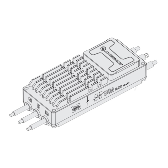
H80A-14S-BLDC-RTF-HW-V2
U S E R M A N U A L
01
Precaution
• Before connecting ESC to the related components, please ensure that all contact terminals are well insulated to prevent short circuit from damaging the ESC.
• Ensure proper connection for the aircraft to operate normally and prevent unpredictable damage to the equipment.
• Before using this ESC, please review the manual to ensure that the power system is correctly matched to avoid damage to the ESC due to wrong connectivity.
• Use only hi-power soldering station that is reliable for soldering work on the ESC.
• Do not use it when the external ambient temperature exceeds 65°C. The high temperature will destroy the ESC and may cause damage to the motor, and cause the machine to explode
• If you need to change the direction of rotation of the motor, you can change the sequence of any two-phase wires.
• The ESC is equipped with CAN function. When using the CAN function, the ESC ID and the throttle channel of the same aircraft cannot be the same, otherwise, the multiple ESCs will be recognized
as the same.
• The ESC doesn't have the CAN terminal resistor.
02
Feature of product
• Multi-rotor dedicated core program, the throttle response speed is greatly improved.
• A built-in memory chip that records the ESC running data in real time and provides the black box function.
• This ESC is equipped with nano-coating technology with a protection level of IP55, and IP67 can be customized.
• The microprocessor is powered by an independent voltage regulator IC, which has better anti-interference ability and greatly reduces the possibility of control loss.
• Uses shielded wires to improve anti-interference, shield external and self-interference, and improves signal quality.
• BLDC square wave drive technology, good compatibility, a program can be compatible with a variety of motors.
• Using CAN communication, the input and output throttle, motor speed, bus current, bus voltage, capacitor temperature, MOS temperature, ESC status and other data can be monitored in real time.
The communication protocol can be obtained by contacting Hobbywing.
• The factory default settings can meet the requirements of most applications with automatically adjustable timing, and is highly intelligent.
• Compatible with various flight controllers and throttle signals with a refresh rate of 50~500Hz.
• Using DEO (Driving Efficiency Optimization) drive technology, it has better throttle linearity and higher drive efficiency.
• You can use DataLink (optional) to upgrade the ESC program. For details, refer to the Datalink instruction manual or contact the manufacturer.
• Support flight controller upgrade ESC firmware. (Requires the use of flight controller)
• Throttle pulse width 1100-1940µs, solidified pulse width, not calibrated.
03
Product specification
Continuous current
Model
Cooling wind speed 7m/s
XRotor Pro-H80A-14S-BLDC-RTF-HW-V2
40A
04
User Guide
Warning! The DEO function of is default turned on, and closing the throttle has a braking effect and reverse-series voltage. Please do not use a power supply device that cannot absorb reverse-series
voltage for ESC testing, otherwise the ESC and power supply will be damaged.
Electronic Speed Controller
Motor
• The black and white wires are the ESC throttle signal cable, the black wire is the GND, and the white wire is the throttle signal wire;
• The yellow, gray and green wires are the ESC data cable and upgrade cable, using CAN bus communication, the yellow wire is the GND, the gray wire is CH, and the green wire is CL;
IMPORTANT
• The CAN cable is also a digital throttle cable and can be used in parallel.
05
Normal boot process
Turn on the remote control, push the throttle
Connect the system to the battery, and the motor will beep "♪123", indicating that the power system is ready, the self-test is over, and you
stick to the lowest point.
can take off at any time.
SHENZHEN HOBBYWING TECHNOLOGY Co., LTD. ・ 101-402 Building 4, Yasen Chuangxin Hi-tech Industrial Park, 8 Chengxin Road, Baolong Industrial Town, Longgang District, Shenzhen, China.
Thank you for purchasing this product! Please read the following statement
carefully before use and, once used, it is considered to be an acceptance of all
ATTENTION
the contents. Please strictly observe and adhere to the manual installation with
this product. Unauthorized modification may result in personal injury and
product damage. We reserve the rights to update the design and performance
CAUTIONS
of the product without notice.
20231007
Number of lithium
battery cells
Specification
BEC
Parameter options
(Standard voltage 3.7V)
80A
None
6-14S
Unable to change parameters
Receiver
UBEC
06
Protection function description
This ESC is specially designed for industrial drones without low-voltage protection and over-heat protection.
1) Start protection:
When the motor fails to start normally within two seconds after pushing the accelerator, the ESC will shut down and the throttle stick must be placed at the lowest point again before it can be
restarted. (The reason for this may be poor connection between the ESC and the motor or disconnected individual output wires, motor stalled, propeller blocked, etc.).
2) Stall protection:
When the ESC detects that the motor is blocked, the ESC will completely turn off the output and repeatedly try to restart the motor. If failed restart, please check the faults. The power output can
only be resumed after the power is turned off and restarted, and the fault is eliminated.
3) Current protection:
When the instantaneous phase current is over 400A, the ESC will turn off the output and keep trying to restart the motor. If the motor does not restart, it will return to normal after power on again.
4) Over-heat warning:
This ESC has no over-heat protection. The warning will be sent through the data interface when temperature is too high and when it is more than 110°C. When the temperature of the ESC is higher
than 130°C, electronic components may be damaged. Please land the aircraft immediately or reduce the throttle output.
5) Low voltage protection:
This ESC has no low-voltage protection. Some electronic components of the ESC will work abnormally when the voltage falls below 18V. Please land the aircraft immediately.
6) Throttle signal loss protection:
When the ESC detects that the throttle signal is lost, the output will be turned off immediately to avoid greater losses caused by the continued high-speed rotation of the propeller. After the signal is
restored, the ESC will resume normal operation immediately.
07
ID setting
If there is no requirement, the default factory ID of the ESC is 1, the throttle channel is 1, and the bus speed is 500KHz.
This function requires the additional purchase of DataLink data box.
Before using this function, ensure that the computer system has installed Micosoft Visual C++ 2013 software in advance, otherwise it cannot operate normally.
1) Connection
ESC---->DataLink data box "yellow gray green"---->"—CH1 CL1";
Connect the data box to the computer via USB.
When changing the ID, please remove the paddle to avoid danger.
For the same aircraft, different ESC IDs and throttles cannot be the same to avoid same ID recognizing as one ESC when using CAN function.
2) Operating diagram
The ESC CAN cable is connected to the DataLink data
box, and the data box is connected to the computer.
Enter the CAN parameter adjustment
page.
Check the page prompt to confirm whether the
setting is successful.
08
Firmware upgrade
Firmware upgrade is divided into two ways: computer online upgrade and flight controller remote upgrade. It supports online upgrade of multiple ESCs at the same time, and the upgrade port is
CAN-ESC (Fast).
The flight control upgrade requires the use of flight control, and is not explained here.
This function needs to use DataLink data box, special DataLink software for upgrade package, and USB data cable.
DataLink data box version requirements, LINK-01.2.15-C or later; DataLink software can be obtained from Hobbywing official website, distributors, Hobbywing sales, and Hobbywing after-sales.
Note: Before using this function, please ensure that the computer has installed Micosoft Visual C++ 2013 software, otherwise it cannot be used. An upgrade package usually only contains one program
Weight
volume
for one ESC. For other ESCs, please obtain a new upgrade package. For details, please refer to the DataLink user manual.
(without wire)
(mm)
1) Connection
87g
84 x 35 x 20
Connect the computer and the DataLink data box with the USB data cable.
ESC---->DataLink data box "yellow gray green"---->"—CH1 CL1".
2) Firmware acquisition
It can be obtained at the place of purchase, Hobbywing official website, dealers, Hobbywing sales and Hobbywing after-sales offices.
Note: It can only be upgraded from the existing program, and software and hardware cannot be upgraded together.
3) Operating diagram
Run the DataLink software.
Select the "Scan" button first, and then
power on the ESC.
Wait for the upgrade to complete, if the
upgrade fails, please repeat the previous
part of the operation.
Battery
09
Common Faults and Prompt Sound Description
Warning tone description.
SYMPTOM
Motor fails to start after power on
Motor fails to start after power on
The power-on voltage is lower than18 V
The power-on voltage is higher than 65 V
Motor stops or restarts during operation
No sound during self-test, motor is operating
Motor fails to start normally, accompanied by
"jam" vibration
Enter the software page, confirm the software version of DateLink in the type
Run DataLink host computer software.
"DataLink", and ensure that the program version is LINK-01.2.15-C.
Wait for the bus rate to be automatically
set, and the ESC is connected to the
Set ID and Throttle.
power supply.
The equipment is powered off, there is no sequence of
power outages, and the equipment will not be burned.
The USB cable is connected to the data
Click "DataLink" of the software,
box, and the ESC is connected to the
View data box firmware, firmware version
DataLink data box.
LINK-01.2.15-C or later.
After the channel on the page is
After the hardware and firmware information
appears on the page.
ticked, select the "Stop" button.
After the upgrade is complete, please
The equipment is powered off, there is no
scan again to confirm that the program
sequence of power outages, and the
is upgraded successfully.
equipment will not be burned.
TONE
POSSIBLE CAUSES
"Beep beep beep" rapid monotone
Throttel is not reset to zero
No throttle signal input on the receiver
"Beep, Beep, Beep" (1 second for each interval)
throttle channel.
Battery voltage is too low.
"Beep, Beep, Beep" (1 second for each interval)
"Beep, Beep, Beep" (1 second for each interval)
Battery volatage is too high.
Motor is not compatible with the ESC.
No sound during self-test, motor is operating
Abnormal drive.
No sound during self-test, motor is not operating
Loss of motor phase.
Click "Set ID and Throttle Channel" and
wait for the data to be saved.
Click "CAN->ESC(FAST)", ESC
firmware upgrade page, click "ESC
communication settings".
In "Available Version", select the
desired firmware and click "Update".
POSSIBLE SOLUTIONS
Push the throttle to the lowest point or recalibrate
the throttle point.
Check if transmitter and receiver is normal. Check
if wiring of throttle channel is normal.
Replace with a full-charged battery.
Replace with a suitable and fully-charge battery.
Replace motor, or propeller.
1. Replace ESC;
2. Return to factory for repair.
1. Check phase connection;
2. Check motor;
3. Return to factory for repair.
October 07, 2023
Advertisement

Related Manuals for Hobbywing X-Rotor Pro H80A-14S-BLDC-RTF-HW-V2

Summary of Contents for Hobbywing X-Rotor Pro H80A-14S-BLDC-RTF-HW-V2
- Page 1 Connect the system to the battery, and the motor will beep "♪123", indicating that the power system is ready, the self-test is over, and you stick to the lowest point. can take off at any time. SHENZHEN HOBBYWING TECHNOLOGY Co., LTD. ・ 101-402 Building 4, Yasen Chuangxin Hi-tech Industrial Park, 8 Chengxin Road, Baolong Industrial Town, Longgang District, Shenzhen, China. October 07, 2023...
- Page 2 感谢您购买本产品!无刷动力系统功率强大,错误的使用可能导致 保护功能说明 人身伤害或者设备损坏,为此我们强烈建议您在使用设备前仔细阅 ATTENTION 读本说明书,并严格遵守规定的操作程序。我们不承担因使用本产 品或擅自对产品进行改造所引起的任何责任,包括但不限于对附带 本电调专为行业无人机设计,无低压保护、无过温保护。 损失或间接损失的赔偿责任。 1) 启动保护: CAUTIONS H80A-14S-BLDC-RTF-HW-V2 当加大油门后两秒内未能正常启动马达,电调将关闭动力输出,油门摇杆需再次置于最低点后才可以重新启动。(出现这种情况的原因可能有:电调和马达连线接触不良或有个别 使 用 说 明 书 输出线断开、电机堵转、螺旋桨被阻挡等)。 2) 堵转保护: 当电调检测到电机发生堵转时,2秒后电调会彻底关闭输出并重复尝试重启电机,如果电机重新启动失败,请仔细排查故障,并重新上电后才能恢复动力输出。 3) 电流保护: 当瞬间电流异常并超过400A时,电调会关闭输出并一直尝试重启电机,若使电机多次重启失败,重新上电后可恢复正常。 4) 过温警告: 当MOS温度高于110°C或者电容温度大于100°C时,会通过数据接口向外发送过温故障信息。当电调报过温故障时,如果温度继续上升,可能导致电子元器件损坏,请及时降落飞行器 或者减少油门输出。 5) 低压保护: 电调无低压保护,当电压低于18V后,电调部分电子元器件会工作异常,请及时降落飞行器。 6) 油门信号丢失保护: 20231007 当电调检测到油门信号丢失将立即关闭输出,以免因螺旋桨继续高速转动而造成更大的损失。信号恢复后,电调也随即恢复正常工作。 注意事项 ID设置 ・电调与相关部件连接前,请确保所有接触端绝缘良好,短路会毁坏电调。 ・请务必仔细连接好各部件,若接触不良,您可能无法正常控制飞行器,或出现设备损坏等其他不可预知的情况。 ・使用此电调前,请认真查看电调以及电机说明书,确保动力系统搭配合理,避免错误的搭配导致损害电调。...
Need help?
Do you have a question about the X-Rotor Pro H80A-14S-BLDC-RTF-HW-V2 and is the answer not in the manual?
Questions and answers