
Summary of Contents for ROBIN WOOD Clima600
- Page 1 Clima600 200x90x55mm 180x132x60mm Weather-dependent Heating circuit controller / heating controller Page 1 / 28 Clima600 Manual V1.0...
- Page 2 Investment schemes Page 2 / 28 Clima600 Manual V1.0...
-
Page 3: Installation
In addition, an additional heat generator (eg LT boiler) can be requested via the CLIMA600. Select the appropriate investment scheme from the description below. The individual parameters are set using the menu navigation. When starting up for the first time, the position of the mixer is “CLOSED”. -
Page 4: Electrical Connections
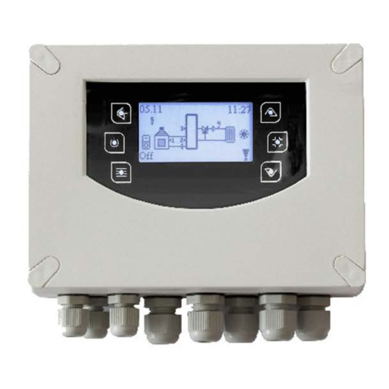
Browse through the menu – increase or decrease in value Enter in the menu / Save in the menu Exit the menu Date-time / temperature sensor display / activate clock program ON/OFF Fig. 3 LCD control panel Page 4 / 28 Clima600 Manual V1.0... - Page 5 Sensor temperature S2 (buffer tank sensor) higher than thermostat THS203 menu The menu system is divided into: Expert Menu(all parameters of the Clima600 can be changed) Consumer menu(only selected parameters may be changed by the end user) 5.1 Expert Menu...
- Page 6 All thermostats and hysteresis are displayed in this level. 5.6 Parameters menu All timers, active counters and values for the selected system scheme are displayed in this level. 5.7 Functions menu displayed. All functions are in this level Page 6 / 28 Clima600 Manual V1.0...
- Page 7 Each time you press the K4 / K6 button, the valve closes / opens by one step. If the selected system scheme does not provide for the use of the outdoor sensor, the Auto, DAY and NIGHT modes cannot be activated. Page 7 / 28 Clima600 Manual V1.0...
- Page 8 Each time you press the K4 / K6 button, the valve closes / opens by one step. If the selected system scheme does not provide for the use of the outdoor sensor, the Auto, DAY and NIGHT modes cannot be activated. Page 8 / 28 Clima600 Manual V1.0...
- Page 9 00:00 00:00 • Weekend clock program:From Mon.-Fri. and Saturday-Sun. 3 time windows are displayed each time. program Mon-Fri Mon-Fri Sam Son Week 06:30 08:00 weekend 12:00 pm 2:00 pm 10:00 pm 6:00 pm Page 9 / 28 Clima600 Manual V1.0...
- Page 10 Checking time/waiting time for the temperature change on sensor S4 (sec.) TIM004 TIM008 Running time of the individual STEP (sec.) when closing the mixer (recommendation value=3) TIM009 Running time of the individual STEP (sec.) when opening the mixer (recommendation value=3) Page 10 / 28 Clima600 Manual V1.0...
- Page 11 The parameterENA018 activates the domestic hot water priority over the heating circuit. If ENA018 = 1and there is a demand for domestic hot water, the pump is OFF and the mixer closes. Page 11 / 28 Clima600 Manual V1.0...
-
Page 12: Outdoor Sensor
-9°C, then THS400 = 63°C during the day and THS400 = 55°C during the night. The THS406 thermostat (and the HYS406 hysteresis) limit the maximum flow temperature. The pump is active. Switches off when reaching the THS405 thermostat. At the same time the valve is completely closed. Page 12 / 28 Clima600 Manual V1.0... -
Page 13: Summer Winter
Sensor S2= contact room thermostat open / closed ENA020 OFF: Sensor S2= room sensor PT1000 5.7.12 Antiblock pump DESCRIPTION queues Anti-blocking waiting time (in days) TIM005 Pump working time (in minutes) TIM006 Activate output P1 for the pump anti-blocking function Page 13 / 28 Clima600 Manual V1.0... - Page 14 Hysteresis for the THS300 parameter THS201 Thermostat on sensor S2 to stop the integration in winter (Stop) HYS201 Hysteresis for parameter THS201 ENA015 Activation (in winter) of integration using sensor S2 (double sensor S3 and S2) Page 14 / 28 Clima600 Manual V1.0...
- Page 15 ( Eg if THS109=45°C, THS110=20°C then range: 45 ÷ 65°C ) The PWM signal profile is automatically selected based on the pump to be managed and the following profiles of pumps on the market: Page 15 / 28 Clima600 Manual V1.0...
- Page 16 Activation of the frost protection function of the solar charging pump THS109 Thermostat for activating the PWM signal 2 of the collector pump HYS109 Hysteresis to the thermostat to activate the PWM signal 2 of the collector pump Page 16 / 28 Clima600 Manual V1.0...
- Page 17 HYD130 °C THD320 Differential thermostat (S3-S2) – activation of the loading of the domestic hot water. °C Hysteresis for thermostat THD320 HYD320 °C Differential thermostat (S3-S2) – Zone 2 mixer valve opening THD321 Page 17 / 28 Clima600 Manual V1.0...
- Page 18 °C THS303 Maximum thermostat on S3 for the boiler with solar loading °C Hysteresis for thermostat THS303 HYS303 °C THS304 Minimum thermostat. on S3 to start the pump of the direct heating circuit Page 18 / 28 Clima600 Manual V1.0...
- Page 19 Total closing time of the mixer for the return increase TIM019 Total opening time of the mixer for the return increase TIM020 Observation time of the temperature change on sensor S4 TIM021 Duration of the individual steps for closing the return valve Page 19 / 28 Clima600 Manual V1.0...
- Page 20 Activation of output P3 to control the anti-block pump function Activation of output P4 to control the anti-block pump function Activation of output P5 to control the anti-block pump function Activation of output P6 to control the anti-block pump function Page 20 / 28 Clima600 Manual V1.0...
- Page 21 PWM1 32 PWM1 pump P6 Sensor wood boiler 4pm - 5pm Sensor buffer bottom 6pm - 7pm Sensor buffer center 8pm - 9pm 22 - 23 Heating circuit flow sensor 24-25 Thermostat/room sensor Page 21 / 28 Clima600 Manual V1.0...
- Page 22 PWM1 32 PWM1 pump P6 Outdoor sensor 4pm - 5pm Sensor buffer bottom 6pm - 7pm Sensor buffer center 8pm - 9pm 22 - 23 Heating circuit flow sensor 24-25 Sensor buffer top Page 22 / 28 Clima600 Manual V1.0...
- Page 23 Opening the valve P3-4 Closing the valve PWM1 32 PWM1 pump P6 Outdoor sensor 4pm - 5pm Sensor buffer center 8pm - 9pm 22 - 23 Heating circuit flow sensor 24-25 Thermostat/room sensor Page 23 / 28 Clima600 Manual V1.0...
- Page 24 PWM2 33 PWM2 pump P2 Solar collector sensor 4pm - 5pm Sensor buffer bottom 6pm - 7pm Sensor buffer center 8pm - 9pm 22 - 23 Heating circuit flow sensor 24-25 Sensor buffer top Page 24 / 28 Clima600 Manual V1.0...
- Page 25 PWM2 pump P2 Outdoor sensor 4pm - 5pm Thermostat/room sensor 6pm - 7pm direct heating circuit Sensor buffer center 8pm - 9pm 22 - 23 Heating circuit flow sensor Thermostat/room sensor 24-25 mixed heating circuit Page 25 / 28 Clima600 Manual V1.0...
- Page 26 Sensor buffer bottom 6pm - 7pm Sensor buffer top 8pm - 9pm Sensor return 22 - 23 Wood boiler Thermostat/room sensor 24-25 Direct heating circuit 1 Room thermostat 28 - 29 Direct heating circuit 2 Page 26 / 28 Clima600 Manual V1.0...
- Page 27 6pm - 7pm Sensor buffer top 8pm - 9pm Sensor return 22 - 23 Wood boiler Thermostat/room sensor 24-25 Direct heating circuit System used: _____________________________________________________ Commissioning on: _____________________________________________________ Commissioned by: _____________________________________________________ Installation Notes: _____________________________________________________ Page 27 / 28 Clima600 Manual V1.0...
- Page 28 For this reason, the design, specifications and content may change without notice depending on the product model. Ganzheitliche Energiekonzepte GmbH & Co. KG is not responsible for any incomplete or incorrect information that may exist. Page 28 / 28 Clima600 Manual V1.0...
Need help?
Do you have a question about the Clima600 and is the answer not in the manual?
Questions and answers