Table of Contents
Advertisement
Quick Links
Advertisement
Table of Contents

Summary of Contents for Centrix LX800
- Page 1 LX800 Installer Manual...
-
Page 2: Table Of Contents
1.2.1 ZONE SETTING 1.0 KEY SWITCH ZONE CIRCUIT 1.2.2 ZONE PARTITION 2.0 TAMPER ZONE CIRCUIT 1.2.3 ZONE TRIGGER LX800 LCD KEYPAD ID SETTINGS 1.3 SYSTEM 1.0 KEYPAD ID SETTINGS 1.3.1 UNIT CONTROL 2.0 IO EXPANDER ID SETTINGS 1.3.2 SYSTEM TIMER 3.0 ZONE EXPANDER ID SETTINGS... -
Page 3: Features
FEATURES CONTROL PANEL MOUNTING & CONNECTIONS LX LCD The control panel PCB contains electronic components sensitive to electric charges. Avoid touching 1. 8 fully programmable zones (expandable to 32 zones) any elements on the control panel PCB during installation. When choosing a place to mount the 2. -
Page 4: System Technical Specification
SYSTEM TECHNICAL SPECIFICATION Center Control Box Housing Dimension (width x height x thickness) : 396 x 291 x 83 mm Physical (PCB) : 194 x 112 mm Weight : 3668 g Electrical Voltage Input : 15VDC from adapter Total capacity of power supply : 2.5A Auxiliary/ Strobe Light/ Bell Output : 12VDC, 500mA (max) - Page 5 2-G Switch Terminal Description Module High LX-S2G Terminal Physical (PCB) : 85 x 85 mm Weight (g) : 113 g Electrical Voltage Input : 12VDC Electrical Current Drain : 33mA each Load Rate Current (max) : 1A *The changes of specification may be made without prior notice. SIREN Main Board Terminals &...
-
Page 6: Main Board Terminal & Wiring
MAIN BOARD TERMINAL AND WIRING INSTALLATION AND WIRING Planning Installation The diagram in page 5 shows the basic structure of the alarm system main board. It consists of 42 removable terminal blocks, 4 on board connectors and 1 shunt jumpers on board. The removable terminal blocks are useful for installers to do wiring before connecting it to the main board. -
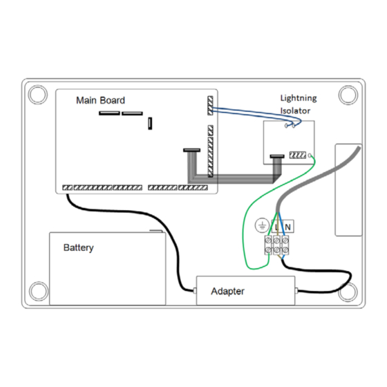
Page 7: Wiring Connection For Lightning Isolator
WIRING CONNECTION FOR LIGHTNING ISOLATOR LX800 LCD KEYPAD WIRING DIAGRAM VOICE E2KEY MODULE MODULE Main Board RING LIGHTNING AP3 COM A1 B1 ISOLATOR PHONE LINE IN CN01 RS485 Connected to NETWORK 230VAC House Phone ZONE EXPANDER 1 Earth Wire Handset... -
Page 8: Zone Circuit
ZONE CIRCUIT LX800 LCD KEYPAD ID SETTINGS KEYPAD ID SETTINGS (LX - LCD) Keypad No. ID Settings 1 2 3 4 Keypad 1 LCD keypad ETTINGS Keypad 2 ID Settings Keypad 3 1 2 3 4 Keypad 4 Keypad 5... -
Page 9: Access Control
LX800 LCD INSTALLER PROGRAMMING Installer Menu Tree To enter into installer programming, key in 12345 (installer code) # ACCESS CONTROL - Changing Installer Pin COMMUNICATION SETTINGS - Setting the communication (reporting) parameters ZONE SETTINGS LX800 LCD KEYPAD - Setting the zone parameters... -
Page 10: Call Reporting
LCD KEYPAD SUB MENU Settings Description 2.1) CALL REPORTING 1) ACCESS CONTROL > Enter New Pin Settings Parameters Default Settings • Re-enter Pin Zone Reporting 1) Alarm Reporting - Enable / Disabl e Enable 2) Alarm Restore Reporting - Disabl e 2) COMMUNICATION SETTINGS Enable / Disabl e Sub Menu... -
Page 11: Telephony Setting
4) SYSTEM SETTING 2.3) TELEPHONY SETTINGS Sub Menu Settings Parameters Default Settings Delay before dial timer 0 - 159 seconds 0 seconds 4.1) Unit Control Dial Type DTMF / Pulse DTMF > Phone Line Communication > Battery Test Dial Attempt 0 - 15 5 dial attempt >... -
Page 12: Voice Setting
5) VOICE SETTING 6.4) SOFT ZONE BELL > Fire, Emergency, Panic Sub Menu • Select Type 5.1) ZONE > Zone 1 to 32 Settings Description ( For 6.1 to 6.4) 5.2) OUTPUT 6.1) Output List > Output 1 to 32 >... -
Page 13: Remote Installer Programming
REMOTE INSTALLER PROGRAMMING REMOTE INSTALLER PROGRAMMING 1) REPORTING Installer can access to system installer programming through telephone dial-in and allowed to alter i) REPORTING OPTION any of the command as shown in installer manual. However, the accessibility to remote installer programming are only available when alarm system are NOT in the following conditions:- ■... -
Page 14: Telephone Number
ii) TELEPHONE NUMBER ■ Account Number 3 ■ Telephone Number 1 Digit position 1-4 = CMS Account Number 4 digits Digit Position 1 – 18 = Telephone number up to 18 digit ■ Account Number 4 ■ Telephone Number 2 Digit position 1-4 = CMS Account Number 4 digits Digit Position 1 –... -
Page 15: Zone
2) ZONE 3) SYSTEM i) ZONE SETTING i) UNIT CONTROL Digit Position Swttings Selections Digit Position Settings Selections Digit position 1 Zone Number (n n) 01 - 32 zones Digit position 1 Disable phone line comm. [0] = No [1] = Yes Digit position 2 Digit position 2 Dynamic battery test... -
Page 16: Key Switch Setting
INSTALLER iii) KEY SWITCH SETTING i) INSTALLER PIN ■ Installer PIN Edit Digit Position Settings Selections Digit position 1 Key Switch Settings 1 [1] Key Switch latch with bell indication SYSTEM REPORTING [2] Key Switch Latch with strobe indication [3] Key Switch Momentary with bell indication The system is able to communicate with CMS or user via telephone line. -
Page 17: Glossary
GLOSSARY TELEPHONE COMMUNICATION Zone Control How to setup Telephone Communication Zone Respond Time – This option determines the sensitivity of each zone After the telephone line is connected to the system, it’s the time to setup the phone communication between the system and user or CMS. Here are the quick steps or guidance to setup the setting for phone communication: Zone Type Interior Zone –...
Need help?
Do you have a question about the LX800 and is the answer not in the manual?
Questions and answers