Advertisement
Quick Links
Programmable Thermostat
WARNING
• Ensure that the electrical power circuit and control output circuit is
suitably protected and fused for your application.
• Ensure all electrical connections are secure and checked before any
power to the device is turned on. Failure to connect correctly may cause
damage to your controller or system, electrical shock or fire.
• Use this instrument only within the scope of its specification otherwise it
may cause damage to your controller or system, electrical shock or fire.
• Do not use this instrument in environments subject to flammable or
explosive gas.
• Do not touch high voltage terminals, such as power supply terminals.
Always isolate the power supply before attempting any adjustments to
the wiring terminals.
• Never disassemble, repair or modify this instrument. This will invalidate
any warranty and could lead to damage to your controller or system,
electrical shock or fire.
Technical Data
Dimensions: 75mm x 33mm x 70mm
Sampling time: 2 times/sec.
Mounting: panel-mounted.
Panel cutout: 71mm x 29mm
Multi input: K/J/Pt100/4~20mA
Output:
TS322
one relay (16A/230V) output and one alarm output (3A/250V)
TS322S
one SSR (14V DC) output and one alarm output (3A/250V)
Control method: ON/OFF control
Accuracy: O.5% F.S.
Display: 3 digits 7 segments LED display
Power consussmption: 3VA max. (Mod. 230V)
Power supply: 21-30VDC or 110-240VAC (Selected when ordering)
Working environment: 0-50°C
Operating & Storage humidity: less than 80%RH (non-condensing)
Order Codes
TS322
One relay output, one alarm, 230V AC supply
TS322S
One SSR output, one alarm, 230V AC supply
TS322A
One relay output, one alarm, 21-30V DC supply
TS322SA
One SSR output, one alarm, 21-30V DC supply
Thermosense Limited
T: +44 (0)1628 531166
E: sales@thermosense.co.uk
TS322 Programmable Thermostat Instruction Manual
Wire Connections
Sensor Input Range
PT100 (°C)
Min
-199
Max
+654
When using 4-20mA Input, use a precision 250 Ω resistor
across terminals 11 and 12 to generate 1-5V input
For 2 wire RTD, white lead 10, red lead 12 and link pin
11 and 12
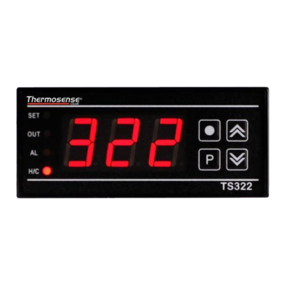
Front Panel
SET - LED will be "ON" when the user is changing the set point.
1
OUT - LED will be "ON" when the Output Relay / SSR drive is active.
2
ALM - LED will be "ON" when the alarm relay is active.
3
H/C - LED will be lit RED when the control action is Heating and
4
GREEN when the control action is Cooling.
Exit key
Press this key to exit from parameter setting mode.
5
6
"UP" and "DOWN" Keys - Press the keys to choose the parameters
and set the values. Press the "UP" key to show the software version.
Function key
7
Press this key 3 seconds to enter set point setting mode.
Press this key 6 seconds to enter parameters setting mode.
W: www.thermosense.co.uk
Type K (°C)
Type J (°C)
-30
-30
+999
+999
v1.0
Advertisement

Related Manuals for Thermosense TS322

Summary of Contents for Thermosense TS322
- Page 1 TS322 Programmable Thermostat Instruction Manual Wire Connections Sensor Input Range PT100 (°C) Type K (°C) Type J (°C) -199 +654 +999 +999 Programmable Thermostat WARNING • Ensure that the electrical power circuit and control output circuit is suitably protected and fused for your application.
- Page 2 TS322 Programmable Thermostat Instruction Manual Input signal selection. Operation Press up or down key to choose the corresponding input sensor. Range: K; J; Pt; mA Default: K Heating and cooling control action selection. Press up or down key to choose the control action.
Need help?
Do you have a question about the TS322 and is the answer not in the manual?
Questions and answers