Advertisement
Quick Links
INSTRUCTION MANUAL
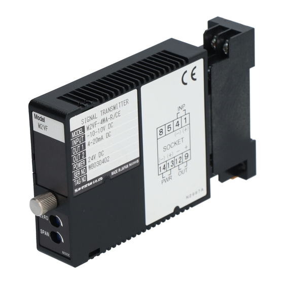
SIGNAL TRANSMITTER
(high-accuracy, ultra-high speed response 30 µsec.)
BEFORE USE ....
Thank you for choosing M-System. Before use, please check
contents of the package you received as outlined below.
If you have any problems or questions with the product,
please contact M-System's Sales Office or representatives.
■ PACKAGE INCLUDES:
Signal conditioner (body + base socket) ............................. (1)
■ MODEL NO.
Confirm Model No. marking on the product to be exactly
what you ordered.
■ INSTRUCTION MANUAL
This manual describes necessary points of caution when
you use this product, including installation, connection and
basic maintenance procedures.
POINTS OF CAUTION
■ CONFORMITY WITH EC DIRECTIVES
• The equipment must be mounted inside a panel.
• Cover the cables (power supply, input and output) using
Shield tubes in order to prevent external noise interfer-
ence. (M-System recommends Nitto Electric Works Co.,Ltd
"MTF - ES Series" products or equivalent.)
■ POWER INPUT RATING & OPERATIONAL RANGE
Locate the power input rating marked on the product and
confirm its operational range as indicated below:
24V DC rating: 24V ±10%, max. 0.6W
■ GENERAL PRECAUTIONS
• Before you remove the unit from its base socket or mount
it, turn off the power supply and input signal for safety.
■ ENVIRONMENT
• Indoor use
• When heavy dust or metal particles are present in the air,
install the unit inside proper housing with sufficient ven-
tilation.
• Do not install the unit where it is subjected to continuous
vibration. Do not subject the unit to physical impact.
• Environmental temperature must be within -5 to +55°C
(23 to 131°F) with relative humidity within 30 to 90% RH
in order to ensure adequate life span and operation.
• Be sure that the ventilation slits are not covered with ca-
bles, etc.
■ WIRING
• Do not install cables (power supply, input and output)
close to noise sources (relay drive cable, high frequency
line, etc.).
• Do not bind these cables together with those in which
noises are present. Do not install them in the same duct.
MODEL
■ AND ....
• The unit is designed to function as soon as power is sup-
plied, however, a warm up for 10 minutes is required for
satisfying complete performance described in the data
sheet.
• Do not leave the output terminals short-circuited for
a long time. The unit is designed to endure it without
breakdown, however, it may shorten appropriate life du-
ration.
COMPONENT IDENTIFICATION
Body
Power LED
Fixing Screw
Zero Adj.
Span Adj.
INSTALLATION
Loosen the fixing screw at the front of the unit in order to
separate the body from the base socket.
■ DIN RAIL MOUNTING
Set the base socket so that
its DIN rail adaptor is at
the bottom.
Position the
upper hook at the rear side
of base socket on the DIN
rail and push in the lower.
When removing the socket,
push down the DIN rail
adaptor utilizing a minus
screwdriver and pull.
■ WALL MOUNTING
Refer to "EXTERNAL DI-
MENSIONS."
M2VF3
M2VF3
Base Socket
Connection
Diagram
Specifications
DIN Rail
35mm wide
Spring Loaded
DIN Rail Adaptor
EM-5107
P. 1 / 2
Advertisement

Related Manuals for M-system M2VF3


Summary of Contents for M-system M2VF3
- Page 1 • The unit is designed to function as soon as power is sup- plied, however, a warm up for 10 minutes is required for Thank you for choosing M-System. Before use, please check satisfying complete performance described in the data contents of the package you received as outlined below.
- Page 2 M-System’s option, the repair, replacement or refund of the purchase price of any M-System product which is defective under the terms of this warranty. To submit a claim under this warranty, the purchaser must return, at its expense, the defective M-System product to the below address together with a copy of its original sales invoice.
Need help?
Do you have a question about the M2VF3 and is the answer not in the manual?
Questions and answers