
Summary of Contents for Severn Trent 1410 Series
- Page 1 Instruction Manual — Automatic Gas Control Valve, Series 1410 APITAL ONTROLS Wall Mounted Automatic Gas Control Valve Wall Panel Mounted Automatic Gas Control Valve - 1 - 100.6100.7...
- Page 2 These instructions generally describe the installation, operation, and maintenance of subject equipment. Capital Controls Company reserves the right to make engineering refinements that may not be described herein. Should any questions arise that cannot be answered specifically by these instructions, they should be directed to Capital Controls Company or our sales agent for a response.
-
Page 3: Table Of Contents
Table of Contents SAFETY ..................4 INTRODUCTION . -
Page 4: Safety
SAFETY The recommended operating procedures have been designed with careful attention to safety. Capital Controls has made formal safety reviews of the initial design and any subsequent changes. This procedure is followed for all new products and covers areas in addition to those included in applicable safety standards. Regardless of these efforts, it is not possible to eliminate all hazards from the equipment or to foresee every possible hazard which may occur. -
Page 5: Introduction
INTRODUCTION General These instructions apply to the wall and panel mounted Series 1410 Automatic Gas Control Valve. Component instruction manuals and supplemental data are referenced where applicable. Maximum capacity of the valve is related to: the gas being dispensed. the capacity of the vacuum regulator. the capacity of the ejector. -
Page 6: Principle Of Operation
Vacuum Line Connector Size: " 8 " 8 " 2 " 8 " 2 " 8 " 2 " 8 " 4 " 8 " 4 " 1 Principle of Operation Install the Automatic Gas Control Valve or panel between the vacuum regulator (or switchover module, if provided) and the ejector or chemical induction unit. -
Page 7: Automatic Gas Control Valve Flow Diagram
Figure 1 - Automatic Gas Control Valve Flow Diagram - 7 - 100.6100.7... -
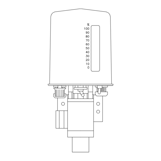
Page 8: Dimensions For Wall Mounted Automatic Gas Control Valve With Dp Regulator
Figure 2 - Dimensions for Wall Mounted Automatic Gas Control Valve with DP Regulator Figure 3 - Dimensions for Panel Mounted Automatic Gas Control Valve 100.6100.7 - 8 -... -
Page 9: Installation
INSTALLATION Mounting The valve or panel should be mounted indoors or under a protective cover, on a vertical, vibration-free surface away from splashing liquid and strong magnetic fields, positioned between the vacuum regulator or switchover module and the ejector. (Refer to Parts Lists 100.7081 and 100.7082 and Figures 2 and 3 for dimensional information.) Mounting holes are provided on each side of the valve bracket or on the four (4) corners of the panel. - Page 10 Figure 4 - Automatic Valve Wiring Diagram Figure 5 - PC board Component Locations 100.6100.7 - 10 -...
-
Page 11: Operation
OPERATION General For operation of the vacuum regulator, process water flow transmitter, ejector or chemical induction unit included in the automatic gas feed system, refer to the appropriate instructions. Start-Up 3.2.1 Use a plastic squeeze bottle 1/4 full of leak test solution to check for gas leaks. Use 26°... -
Page 12: Manual Operation
Table I ) l / Table II ) l / Manual Operation Manual operation is used in the event of a loss of input signal or manual override. Refer to Figure 6. For manual operation, proceed as follows: 3.3.1 Switch the AUTO/MANUAL switch to the MANUAL position. 3.3.2 Move the manual adjustment switch left or right to obtain the desired feed rate (indicated on gas flowmeter). - Page 13 c. Put your finger on the vacuum connector opening and feel the vacuum. There should be no doubt that a vacuum exists. If there is no vacuum, be certain the supply pressure is sufficient and either the nozzle or water/solution piping is not plugged. Correct the condition and obtain proper vacuum before proceeding.
-
Page 14: Automatic Valve Less Cover
Figure 6 - Automatic Valve Less Cover Figure 7 - Valve Bottom Stop 100.6100.7 - 14 -... - Page 15 3.4.4 Electrical Calibration - Refer to Figure 5. NOTE: Check for proper value of RI Resistor Per Table IV. a. Select the desired position for the valve closed output signal. 1. Use N.C. position to drive normally energized gas shutoff solenoids. 2.
- Page 16 3.4.5 Dosage and Deadband (DB) Adjustment (Refer to Figure 5) a. Adjust input signal per Table IV for 90% flow. b. Set dosage control knob approximately halfway (midrange). c. Adjust DB potentiometer clockwise until the valve oscillates or “hunts”, then counterclockwise until oscillation stops, then adjust DB counterclockwise approximately 10°...
-
Page 17: Service
SERVICE NOTE: DUE TO THE NATURE OF THIS EQUIPMENT AND THE USE OF CUSTOM-BUILD ELEMENTS, IT IS RECOMMENDED THAT THIS EQUIPMENT BE RETURNED TO THE FACTORY FOR REPAIR OR REPLACEMENT IF FOUND TO BE DEFECTIVE IN FORM OR FUNCTION. Cleaning Slotted Valve Plug (Refer to Figure 9) 4.1.1 Evacuate all gas from the system before disassembly. -
Page 18: Disassembled Valve
4.2.11 Rotate the motor gears manually and observe the feedback potentiometer gear for proper operation. 4.2.12 Confirm calibration or recalibrate as required. 4.2.13 Replace valve cover. Figure 9 - Disassembled Valve 100.6100.7 - 18 -... -
Page 19: Troubleshooting Chart
TROUBLESHOOTING CHART c i f c i f t s i n i l . y r c i f c i f n i l l n i . y r g i l l n i l n i . - Page 20 t a i l l a n i l n i l l l a e i l n i l l l a c i f n i l y l f t t i . y l l l i .
- Page 21 c i t t i s t t i n i l . t r y t i - 21 - 100.6100.7...
- Page 22 December 12, 2000 Design improvements may be made without notice. Represented by: APITAL ONTROLS Severn Trent Services, Inc. 3000 Advance Lane Colmar, PA 18915 • 1-800-227-2273 • Tel: 215-997-4000 • Fax: 215-997-4062 Web: www.capitalcontrols.com E-mail: marketing@capitalcontrols.com • UNITED KINGDOM • UNITED STATES • HONG KONG •...
Need help?
Do you have a question about the 1410 Series and is the answer not in the manual?
Questions and answers