
Summary of Contents for Bridgecom Systems BDR-50
- Page 1 BDR-50 DMR Digital-Analog Repeater Note: Ext I/O not functional Note: IP Network Option not functional or available BridgeCom Systems 816-532-8451 www.bridgecomsystems.com 113 South Bridge Street Smithville, MO 64089...
-
Page 2: Table Of Contents
INDICATATION OF TRANSIT SOFTWARE OPERATION PANEL KEY OPERATION AND DIGITAL DISPLAY Thanks for choosing our repeater. PANEL OPERATION OVERALL FRAMEWORK Best Regards. SET UP DISPLAY PASSWORD AUTHENTICATION BridgeCom Systems SHORTCUTS TROUBLESHOOTING GUIDE SPECIFICATIONS 20,21 WARRANTY... -
Page 3: User Instructions
♦ Please keep these instructions for future reference. burns. ♦ BridgeCom Systems reserves the right to make changes, ♦ The repeater shall be maintained by professionals. Do not attempt additions and modifications without prior notice. This manual is to open enclosure and self-service unless qualified. -
Page 4: Open-Package Inspection
An green Always on, the repeater is receiving signals electronic version of this manual is located on the BridgeCom Systems green Always on, the link is successful Support page. -
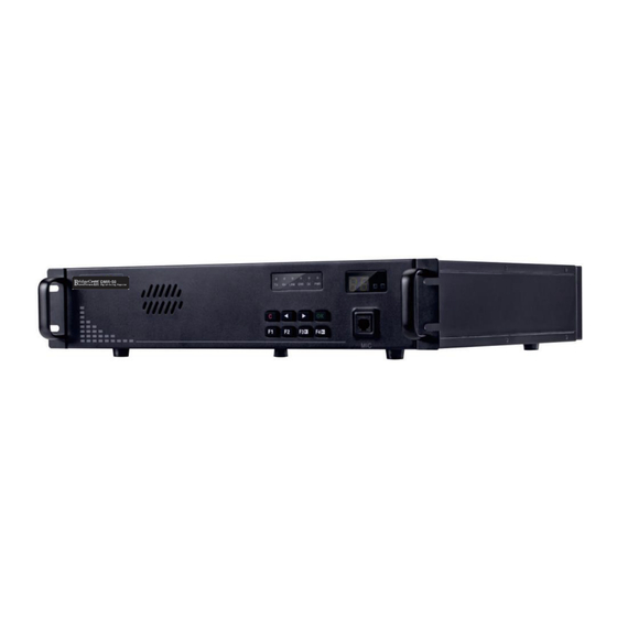
Page 5: Back Panel Introduction
Back panel introduction Rear panel EXT-I/0 port def nition (not functional) Rear view Pin No. Definition 26 Pin Description Pin1 -13v Power Outside interface picture Pin2 O_CLKX CLKX output a LVTTL_3.3V signal via optical coupler (MsBSP Clocking) Pin3 UART3_RX UART3_RX serial port receiving Power supply interface and switch picture Rear panel port introduction Pin4... - Page 6 Introduction of Functions Pin No. Definition 26 Pin Description 1). DMR digital audio transmit (McBSP) Frame Synchronization receive (input) a signal Pin22 IO_FSR LVTTL_3.3V via optical coupler When the RX port of the repeater receives an uplink signal from a device, Pin23 Digital Ground the repeater will transmit via its TX port if it meets the programmed...
-
Page 7: Repeater Operation
3. RX / TX Indicators When the repeater is operational, the TX/ RX indicators and A/ B slot Please refer to BDR-50 repeater programming software to set up indicators will light. If "A" is illuminated then slot #1 is in use. "B"... - Page 8 b). Inbound Code: defines the numeric values (0 to 9) used to access the 075526000000, press the PTT button, input 222# on keyboard, then repeater via phone line from the outside. release PTT, after a few seconds you can have a call with Outbound Code: defines the numeric values (0 to 9) used to access the 075526000000.
-
Page 9: Panel Operation
Panel basic operation Power-on State When the repeater is powered on and is idle, the display will show the current selected channel number. (Password authentication) Press before will remove the password number you input. 4).ln any menu press , the device will enter password lock state and idle. - Page 10 The digital display shows the current RF power level from L1 to levels correspond as L1 = 5W and L9 = 50 W. The figure shows a setting of L6 or 30 Watts. Press to decrease or increase the power level, alternately displays new level "L1 to L9"...
-
Page 11: Troubleshooting Guide
4). Repeat the process, when the two passwords are the same, the Troubleshooting guide repeater will emit a tone to indicate the entry is correct. The display will Description Reason Solution revert back to P3 indicating that the new password is in effect. If a warning tone is heard then the entry has failed in setting up the new 1.The power... - Page 12 When the repeater has an error, the error light will turn on, and the speaker will emit a warning alarm, display will show the fault code. After the warning, check if the communication is OK, if not, restart th e repeater, if error still occurs, please contact the dealer.
-
Page 13: Warranty
WARRANTY AND SERVICE Limited Warranty This product is warranted by BridgeCom Systems, Inc. to be free of defects in materials and workmanship for a period of two years from the BDR-50 (DC13.6V) date of purchase. If a defective part causes this product to operate improperly during the one-year warranty period, we will service it to the original owner free of charge if shipped to BridgeCom Systems at the owner’s expense.
Need help?
Do you have a question about the BDR-50 and is the answer not in the manual?
Questions and answers