Table of Contents
Advertisement
Quick Links
BULLETIN
754C
I N S TA L L AT I O N & O P E R AT I O N
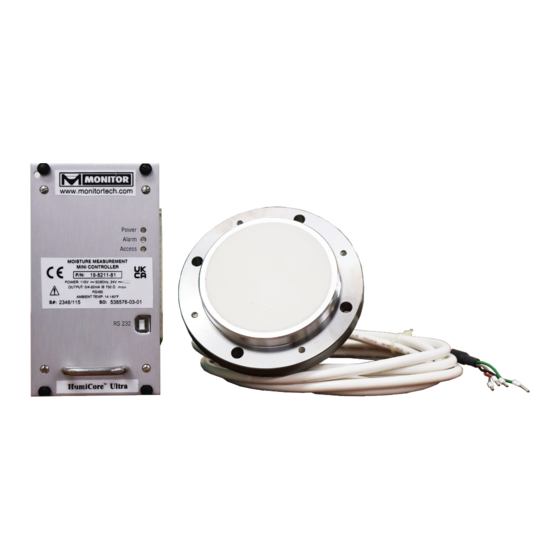
HumiCore™ Ultra Mini
Moisture Measurement System
HumiCore
Ultra Mini
TM
Thank you for purchasing a quality solution from Monitor Technologies LLC. We realize that
you do have a choice of vendors when procuring level measurement equipment and we
sincerely appreciate your business!
This manual contains the information necessary to ensure a safe and successful installa-
tion. Please read and comply with the section on page 16 of this manual pertaining to SAFETY.
Doing so will ensure proper operation of the equipment and the safety of all personnel.
Before discarding the shipping container, please inspect it thoroughly and verify that all parts
ordered are accounted for. Sometimes smaller parts become stuck under carton flaps and
other packaging materials.
In the event that information contained herein does not completely satisfy your requirements
or answer your questions, you may contact our Technical Support personnel on our website
www.monitortech.com, by telephone at 800-766-6486 (630-365-9403), or by e-mail at
techsupport@monitortech.com. If your level measurement system ever requires service either
in or out of warranty, please contact us and obtain an RMA (return material authorization)
number prior to shipping the unit to us.
®
www.monitortech.com
Advertisement
Table of Contents

Subscribe to Our Youtube Channel
Related Manuals for Monitor HumiCore Ultra Mini


Summary of Contents for Monitor HumiCore Ultra Mini
- Page 1 Moisture Measurement System HumiCore Ultra Mini Thank you for purchasing a quality solution from Monitor Technologies LLC. We realize that you do have a choice of vendors when procuring level measurement equipment and we sincerely appreciate your business! This manual contains the information necessary to ensure a safe and successful installa- tion.
-
Page 2: Table Of Contents
TABLE OF CONTENT S Section Page Section Page Introduction to Software HumiCore 6.0 Technical Data of the ........ Ultra Mini (Hu_Config_3019) ....2 Ultra Mini Controller . 20 HumiCore 1.1 Starting the Configuration Program ..7.0 Technical Data of the ........ HumiCore™ Ultra Mini ....2 sensor ......22 HumiCore 1.2 Connect Configuration Program Basic Circuit Diagram ...... -
Page 3: Ultra Mini
HumiCore Ultra Mini 1.2 Connect Configuration Program A connection must exist between the HumiCore Ultra Mini and the PC in order to use the program. Input the interface parameters via the tab ‘Extras’ => ‘PC-settings’ (Fig. 3). HumiCore Fig. 3 You can select the following settings using a drop-down menu: Selection of respective Com port Connection: You can see which Com port you use on the... -
Page 4: The Input Tab
1.3 The Input Tab Taskbar: Symbol bar (from left): User Tabs: File Load Settings Load Settings Products Save Settings Save Settings Analog Outputs Extras Read Device Settings Read Device Settings Digital Inputs Program Parameters Program Parameters Analog Inputs Program Parameters Online Display Compensation and Calibration System Online Display... -
Page 5: The Taskbar 'File
1.4 The Taskbar ‘File’ 1.4.1 Save Settings It is recommended to create a backup file after every calibration of the sensor. To save the new setting, click on the button ‘Save settings’. The window on the left appears to save the settings file. Enter the desired name in the field ‘File name’. -
Page 6: The Taskbar 'Extras
1.5 The Taskbar ‘Extras’ 1.5.1 Read Device Settings Serves to activate a connection of the configuration software to the mini controller (see 1.2). 1.5.2 Program Parameters (Refer to 1.5.3) 1.5.3 Program Parameters and Calibration If one of the variables is changed in the user interface of the software, this is not yet stored in the Ultra Mini system. -
Page 7: The User Tabs
A sensor or transfer error is indicated in the HumiCore online tab with Sensor fault (Fig. 13). The mA value for the analog output jumps to the previously parameterized alarm value. All other measured values are frozen when there is an error and thus do not change any more. Error elimination: Check cable and terminal connections and possibly restart the system. - Page 8 2.1.1 Product Selection In the first field ‘Product Name’ it is possible to manually store the type of product, the batch or a random designation for the product. In the drop-down menu ‘Display’ you can select the desired indication value. The selection options here are: M =>...
- Page 9 2-point-calibration linear behavior: Fig. 16 Fig. 17 3-point-calibration linear behavior: Fig. 18 Fig. 19 The next step is to specify the calibration time. This may vary depending on the process. The factory setting of 10 seconds can be adapted to the process in this step. The 1st calibration point: After specifying the number of calibration points and/or the calibration time, you can start the actual calibration.
- Page 10 The samples taken during the calibration process are now subjected to moisture determination in the laboratory. The resulting values are also combined to form a mean value. The moisture value determined in the laboratory is now manually allocated to the ‘1st calibration point’. This means the first calibration point has been defined.
-
Page 11: Analog Outputs
2.2 Analog Outputs HumiCore Fig. 23 The (measuring) range and the mA values (or V) of the analog outputs are defined in the main tab ‘Analog outputs’. “Current” or “voltage” can be selected as the output signal via a drop-down menu. In doing so, you have to ensure the precise jumper setting (see 9.0 ‘Jumper Settings’... -
Page 12: Digital Inputs
2.3 Digital Inputs HumiCore Fig. 25 The HumiCore Ultra Mini has two digital inputs. Different functions can be performed when the inputs are connected and activated. The digital inputs have to be connected to a control signal of 0 volts or 10 to 24 volts DC. The following functions are available: Measurement STOP: This stops the measurement and freezes the value last indicated. -
Page 13: Analog Inputs
2.4 Analog Inputs HumiCore Fig. 26 The HumiCore Ultra Mini provides two analog inputs. They can be calibrated via the main tab ‘Analog inputs’. The first input is designed for temperature monitoring by means of PT-100. To be able to guarantee smooth monitoring, the respective input signals have to be defined in advance. A PT100 simulator is connected to the input for this purpose. -
Page 14: Compensation
Now the 4 and/or 20 mA input has to be linked to the respective signal. Fig. 26 shows a pressure sensor that outputs a value range from 1-10 bar. The lower 4 mA input is thus linked to 1 bar and the upper value (20 mA) to 10 bar. -
Page 15: System
2.6 System HumiCore Fig. 30 MODBUS Address: The addresses 1 to 255 are available as identifier for the Ultra Mini and can be assigned to the device by means HumiCore of the PC setup program. The HumiCore Ultra Mini always has the address 1 as default value. The transfer speed of the RS232 and RS485 port in the Baud Rate: Ultra Mini is determined by the parameterizable baud rate. -
Page 16: Classification Of The Safety Instructions
3.0 CL ASSIFIC ATION OF THE S AFET Y INS TRUCTIONS This manual contains instructions that you have to observe for your personal safety as well as to avoid material damage. These instructions are highlighted using a triangular warning sign and shown as follows, depending on the degree of risk. -
Page 17: General Instructions
Moreover, we point out that the content of the manual shall not constitute part of or amend a previous or existing contract, agreement or legal relationship. All obligations of Monitor Technologies LLC shall result from the respective contract of purchase, which also contains the complete and solely valid warranty terms. -
Page 18: Introduction To Hardware
4.0 INTRODUCTION TO HARDWARE The HumiCore Ultra Mini system consists of the HumiCore Ultra Mini controller and the HumiCore sensor. The inline measuring system for process monitoring guarantees trouble-free measurement of the internal product moisture of solids and emulsions. A PC-aided user interface with a clearly arranged display of the measured alarm and MIN/MAX values, combined with easy editing and parameterization, enables uncomplicated and simple operation. -
Page 19: Description Of The ..................................... Humicore Tm
5.0 DESCRIPTION OF THE HUMICORE SENSOR The HumiCore sensor for capacitive moisture measurement is based on the open capacitor principle. The bulk material in front of the measuring window serves as the dielectric of the measuring capacitor. Data processing of the raw measured values with temperature compensation already takes place in the moisture sensor. -
Page 20: Humicore Tm Ultra Mini Controller
6.0 TECHNIC AL DATA OF THE HUMICORE ULTRA MINI CONTROLLER 24 products (optionally up to 100 products) Product Memory: ANALOG OUTPUT AO-1 (moisture), AO-2 (temperature) For the analog outputs, a filter of the 1st order (0.1 - 9.9)s can be parameterized. Galvanic separation between the analog outputs, to the auxiliary energy and to all other inputs/outputs. Constant current Voltage 0...22 or 22...0 mA... - Page 21 Pt100-INPUT / mA-INPUT AI-1 for ext. temperature compensation For the two inputs, there is no galvanic separation from the inner circuitry. 2 or 3-core-switch Pt100-connection: 32°F to 212°F (0°C to +100°C) Measuring Range: 0/4 – 20 mA according to 32°F - 212°F (0 – 100°C) mA-range: Ultra Mini INTERFACES RS232, RS485 FROM HumiCore Galvanic separation of the RS232/RS485 to the auxiliary energy and to all other inputs/outputs.
-
Page 22: Tm Sensor
7.0 TECHNIC AL DATA OF THE H ™ SENSOR u m i o r e ELECTRICAL DATA 20 VDC, 20 mA Supply: Half-duplex Digital Interface: 19200 bps, 1 Baudrate/Device Address: 0.4 W Power Consumption: MECHANICAL DATA St. s 1.4301 Housing: IP 67 according to EN 60529 Protection Class: ca. -
Page 23: Humicore
8.0 BASIC CIRCUIT DIAGRAM HumiCore™ Fig. 34... -
Page 24: Jumper Settings
9.0 JUMPER SETTINGS Termination of the RS485-interface: For termination of the RS485-interface, the jumpers JP1/JP2 have to be closed. Switching the analog outputs from constant current to voltage: The jumper JP3 for AO1 or JP4 for AO2 switches from constant current (JP3/JP4 open) to voltage (JP3/JP4 closed). Fig. 9 Fig. -
Page 25: Cable Connection Of The .......................... Humicore Tm Ultra Mini Sensor
10.0 C ABLE CONNECTION OF THE HUMICORE SENSOR Fig. 37 DO NOT CONNECT THE CABLE SHIELD; LEAVE THE SHIELD UNCONNECTED WHEN WIRING THE SENSOR TO THE ULTRA MINI CONTROLLER. The shield is already connected internally to the sensor’s chassis. If a large potential was to exist between the connection point and the sensor chassis, this would induce a large amount of electrical current in the shield that could result in interference. -
Page 26: Desktop Housing
11.0 TERMIN AL ASSIGNMENT FOR THE DESK TOP HOUSING Fig. 38 HumiCore Sensor... -
Page 27: Assignment Of The Female Connector For The Mini Controller
12.0 ASSIGNMENT OF THE FEMALE CONNECTOR FOR THE MINI CONTROLLER Mini Controller Fig. 39 HumiCore RS485 Interface Connections... -
Page 28: Mounting Instructions And ...................... Installation Example ............................. 28
13.0 MOUNTING INS TRUCTIONS AND INS TALL ATION EXAMPLES The HumiCore sensor is designed for continuous moisture measurement in production flow. A prerequisite for correct moisture measurement in bulk materials is always to select the right place to install the moisture sensor. In connection with bulk material chutes or conveyor belts, you additionally have to ensure that the material to be measured is fed over the sensor at a constant layer height as far as possible. -
Page 29: Indirect Mounting
13.2 Indirect Mounting Indirect installation of the HumiCore sensor is necessary if the wall thickness is 0.39” (10 mm) or more or the wall is curved. In such cases use of a welded flange is recommended and available as an accessory. Weld Fillet Mounting studs with nuts &... -
Page 30: Mounting At A Conveyor Belt
Sled Example (Optional) Ship Example (Optional) Fig. 44 14.0 WARRANT Y Monitor Technologies LLC warrants each HumiCore™ Ultra Mini moisture measurement system it manufactures to be free from defects in material and workmanship under normal use and service within two (2) years from the date of purchase. The purchaser must give notice of any defect to Monitor within the warranty period, return the product intact and pre-pay transportation charges. The obligation of Monitor Technologies LLC under warranty is limited to repair or replacement at its factory. This warranty shall not apply to any product which is repaired or altered outside of the Monitor Technologies LLC factory, or which has been subject to misuse, negligence, accident, incorrect wiring by others or improper installation. Monitor Technologies LLC reserves the right to change the design and/or specifications without prior notice.
Need help?
Do you have a question about the HumiCore Ultra Mini and is the answer not in the manual?
Questions and answers