Table of Contents
Advertisement
Quick Links
Advertisement
Table of Contents

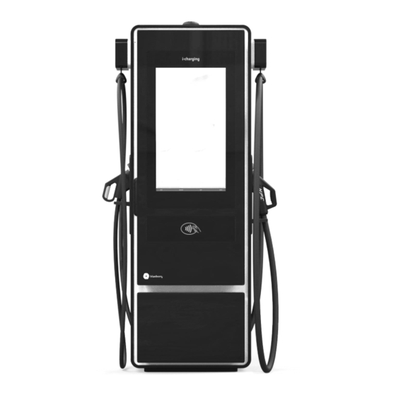
Summary of Contents for CHARGESTAR Blueberry 50 kW
- Page 1 Service Manual PRODUCT DOCUMENTATION 1.0...
-
Page 2: Customer Care
MANUFACTURER Address Phone E-mail Website Rua de Serralves, 351 4150-707 +351 221 150 960 info@i-charging.pt www.i-charging.pt Porto, Portugal CUSTOMER CARE E-mail customer.care@i-charging.pt... - Page 4 INDEX ABOUT THE MANUAL SAFETY INSTRUCTIONS 2.1. Safety Notices START-UP 3.1. Commissioning 3.1. Operator Sealing 3.2. Troubleshooting...
- Page 5 blueberry Service Manual 1.0...
-
Page 6: About The Manual
ABOUT THE MANUAL The purpose of this manual is to provide the steps and settings required for commissioning, configuration and troubleshooting of blueberry line chargers. Please make sure that this manual is carefully read and ensure that all safety notices given are followed. -
Page 7: Safety Instructions
SAFETY INSTRUCTIONS This manual must be read carefully before the commissioning, configuration and troubleshooting of the blueberry line chargers. Incorrect operation as a result of non- compliance with the instructions provided by this manual may lead to severe injuries or damages. -
Page 8: Safety Notices
2.1. Safety Notices Special warnings and safety measures may appear throughout this document or on the equipment to warn of potential hazards or to call attention. The symbols carry the following meanings: RISK OF ELECTRIC SHOCK! Procedures marked with this symbol must not be carried out under any circumstances. Actions contrary to these safety notices may lead to severe injury and death. - Page 9 START-UP 3.1. Commissioning PLEASE NOTE! Before performing the next steps, please make sure that the switch disconnector and all the circuit breakers of the equipment are switched on and make sure that you have the username and password needed to sign in the maintenance tool. The first step for the commissioning will be to do the configuration of the charger on the maintenance tool which can be accessed by one of two ways: 1 - Connecting an ethernet cable to the router, on LAN2 or LAN3, and access the url...
- Page 10 After the sign-in, start the process by pressing the button “Start initial configuration” and then “Start system configuration” in the next page: blueberry Service Manual 1.0...
- Page 11 In the next steps, fill in the information that is required: STEP 1 – blueberry charging station identification STEP 2 – Power and charging options STEP 3 – Communications blueberry Service Manual 1.0...
- Page 12 STEP 4 – OCPP Settings STEP 5 – Location STEP 6 – Review of all configurations that were made in the previous steps and initiate sytem blueberry Service Manual 1.0...
- Page 13 Before initiating the system, a validation test shall be made to guarantee that all components are operating correctly: Follow the steps and answer to the questions to check if the blueberry charging station is operating correctly. In the end, the results of the validation test will be available to download. blueberry Service Manual 1.0...
- Page 14 After the initial configuration and if everything is correctly configured, the blueberry charging station will proceed to the initial menu. In case of error, the display will show the message “Out of Service”. If the blueberry has two outputs and only one is correctly configured, the display will show the other output as unavailable.
-
Page 15: Locking System
3.1. Operator Sealing After the commissioning, once the door is closed and the charger is correctly configured, the customer can seal the equipment. For that, a tamper-proof label can be used and shall be placed on half cylinder of the locking system, as shown below. blueberry/ blueberry PLUS - User Unit Power Unit (when applicable) [both sides]... -
Page 16: Troubleshooting
3.2. Troubleshooting To diagnose and correct possible faults, i-charging defined diagnostic trouble codes (DTCs) that will help understanding what is causing the error. The DTC code is a numerical code that depends on the error type and on the component in error. The meaning of each DTC code is shown below: Component ID Cabinet ID... - Page 17 Component Identification: Component Component Firmware Update Power Module 3 Communication Power Module 4 Stop Wire DC contactor 1 Retractor DC contactor 2 Fast Stop DC contactor 3 CCS Interface DC contactor 4 Resistor Code Diode 1 Diode 2 Charge Sequence Diode 3 Charging Signals Diode 4...
- Page 18 Error Identification: Error Error Wire not detected Sensing triggered Overtemperature CCMD triggered Out of Range Output triggered Can Fail (Controller) Power triggered Control Error DC Undercurrent Potentiometer fail Circuit Breaker OFF AC voltage fault Comms Failed AC current fault Configuration Failed Command and feedback Failed mismatch...
- Page 19 Copyright © 2022 i-charging mobilidade elétrica, s.a. All rights reserved. This document is protected by copyright laws and its content is proprietary of i-charging. It may not be reproduced, republished, distributed, or otherwise exploited in any manner without written permission of i-charging.

Need help?
Do you have a question about the Blueberry 50 kW and is the answer not in the manual?
Questions and answers