
Summary of Contents for RITKEEP PMAX-5600
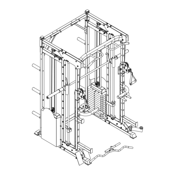
- Page 1 PMAX-5600 SMITH MACHINE USER MANUAL Read all instructions carefully before assembling this product. Retain this owner’s manual for future reference.
-
Page 2: Table Of Contents
TABLE OF CONTENT I. SAFETY INSTRUCTIONS -----------------------------------------1 II. CARE INSTRUCTIONS -------------------------------------------2 III. PARTS LIST -----------------------------------------------------3 IV. ASSEMBLY INSTRUCTION --------------------------------------4 V. EXERCISE GUIDE-----------------------------------------------22 VI. MAINTENANCE-------------------------------------------------24... -
Page 3: Safety Instructions
I. SAFETY INSTRUCTIONS To ensure your safety, read the following precautions before using this product. 1. Please read, study and understand the instructions and all warning labels before use. (It is recommended to be familiar with the normal operation and use methods of the device before using this product. Information is available on this manual and at local retailers). -
Page 4: Care Instructions
II. CARE INSTRUCTIONS 1. Lubricate moving joints with silicon spray after periods of usage. 2. Be careful not to damage plastic or metal parts of the machine with heavy or sharp objects. 3. The machine can be kept clean by wiping it down using dry cloth. 4. -
Page 5: Parts List
III. PARTS LIST... -
Page 6: Assembly Instruction
IV. ASSEMBLY INSTRUCTIONS 1. The gasket shall be placed at both ends of the bolts (against the bolt head and nuts), unless otherwise stated. 2. Preliminary assembly is hand tightening of all bolts and nuts and hand tightening with the wrench for complete assembly. 3. - Page 7 STEP2 1. Place 4 x part (#47) and 4 x part (#16) into part (#1) as pictured.
- Page 8 STEP3 1. Install part (#7) and part (#8) using: 4x part (#71) 8x part (#85)
- Page 9 STEP4 Insert the weight stacks part (#43) into part (#16) as pictured with the holes facing down. Insert part (#21) into the middle, through the weight stacks. Lastly add the part (#42) weight on top of the other weight stacks as pictured.
- Page 11 STEP6 1. Secure 4x part (#19) to parts (#4) and (#5), and secure with 4x part (#79) and 4x part (#85) Attach part (#44) onto part (#19) as pictured and place the collars part (#46) into part (#44). Secure part (#15) onto either post part (#4) or (#5) using: 2x part (#74) - 1x part (#22) 2x part (#83)
- Page 12 STEP7 1. Secure part (#6) to part (#4) and (#7) using: - 2x part (#23) - 4x part (#74) - 8x part (#85) - 4x part (#83) 2. Secure part (#16) onto part (#6) with 2x part (#82). 3. Repeat steps 1 and 2 on the other side.
- Page 13 STEP8 1. Secure part (#11) into part (#7) using: - 1x part (#22) - 2x part (#74) - 4x part (#85) - 2x part (#83) 2. Secure part (#11) to part (#4) using: - 1x part (#22) - 2x part (#74) - 4x part (#85) - 2x part (#83) 3.
- Page 14 STEP9 1. Secure 2x part (#18) onto part (#11) using: - 3x part (#74) - 6x part (#85) - 3x part (#83) 2. Repeat step 1 for the other side. 3. Secure 2x part (#17) onto part (#11) and part 1 using: - 1x part (#74) - 2x part (#85) - 1x part (#83)
- Page 15 STEP10 1. Slide part (#30) into part (#9) post as pictured and (#63). 2. Repeat for the other side. 3. Place part (#9) into part (#18) and (#17) as pictured. 4. Secure part (#17) to part (#9) using: - 2x part (#74) - 4x part (#85) - 2x part (#83) 5.
- Page 16 STEP11 1. Secure part (#12) to the top of part (#18) using: - 4x part (#73) - 8x part (#85) - 4x part (#83) 2. Secure part (#35) and (#36) onto part (#12) using: - 4x part (#79) - 8x part (#85)
- Page 17 STEP12 1. Secure part (#32) onto part (#7) and (#8) using: - 20 x part (#79) pre-installed on part (#32) - 20x part (#85) 2. Attach part (#20) to part (#88), then connect part (#88) with part (#85) onto part (#21), in order as shown. 3.
- Page 18 NOTE: Be sure to install the wire rope before installing the pulley. See next page for pulley assembly instructions.
- Page 19 STEP13 1. Secure the part (#55) on part (#11) using: - 1x part (#77) - 1x part (#83) - 2x part (#85) 2. Secure 2x part (#55) to part (#6) using: - 2x part (#74) - 2x part (#49) - 2x part (#83) - 4x part (#85) 3.
- Page 20 STEP14 1. Secure weight covers 2x part (#25) with 8x part (#78), 8x part (#86). 2. Secure row foot plate part (#33) using: 2x part (#79), 2x part (#85). 3. Secure landmine post part (#45) to part (#40) using: - 1x part (#71) - 2x part (#85) - 1x part (#83) 4.
- Page 21 STEP15 1. Place part (#26) tube into 2x part (#27). 2. Place the 2x part (#27) onto the 2x part (#90) as pictured. 3. Place 2x part (#92) as pictured on part (#90). 4. Place 2x part (#47) onto part (#90). 5.
- Page 22 STEP16 Secure the Smith bar you assembled onto the rack part (#17) and (#18) using: - 8x part (#81) - 16x part (#86) - 8x part (#84) NOTE: Ensure to fully tighten all screws.
- Page 23 OPTIONAL ATTACHMENT Landmine Handlebar Assembly 1. Bolt the landmine barbell bracket to the landmine handles (with screws from the landmine handle). 2. When using with separate barbell. Insert barbell into the barbell bracket and tighten with the nut.
-
Page 24: Exercise Guide
V. EXERCISE GUIDE ATTENTION: Before beginning any exercise program, consult your physician. This is important especially if you are over the age of 45 or individuals with pre- existing health problems. The pulse sensors are not medical devices. Various factors, including the user’s movement, may affect the accuracy of heart rate readings. - Page 25 After warming up, increase the intensity to your desired exercise program. Be sure to maintain your intensity for maximum performance. Breathe regularly and deeply as you exercise. Finish each workout with a light jog or walk for at least 1 minute. Then complete 5 to 10 minutes of stretching to cool down.
-
Page 26: Maintenance
VI. MAINTENANCE MAINTENANCE METHOD: To extend the service life of the device, the parts must be lubricated on time. The product has been initially lubricated before leaving the factory, but lubrication is required between the guide rod and the weight plate over time.
Need help?
Do you have a question about the PMAX-5600 and is the answer not in the manual?
Questions and answers