Table of Contents
Advertisement
Quick Links
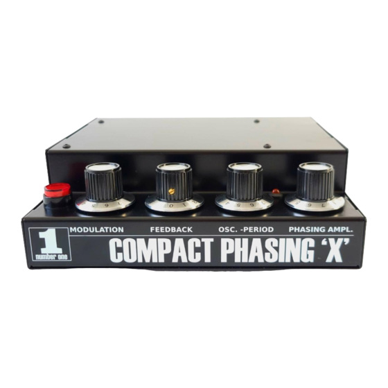
Compact Phasing X user manual v1.1 2023
Originally designed by Gerd Schulte in the 70s in Germany and was called Number One, Compact
phasing A.
Very unique sounding and looking phaser. It works with incandescent light bulbs and light
dependent resistors (LDR). This combination makes it interesting, phasing is not linear, freq
resonance peaks vary and this creates a very playful phasing effect.
There has been few clones around after the original was discontinued. Jürgen Haible made his own
clone and added new functions, but also kept it very close to the original. His boards were also
used by Mode Machines KRP-1.
His work and explanations are still available on his website.
http://jhaible.com/legacy/compact_clone/
This website also has all the build information needed, schematics, partlists etc.
Advertisement
Table of Contents

Summary of Contents for Van Daal Electronics Number One Compact Phasing X
- Page 1 Compact Phasing X user manual v1.1 2023 Originally designed by Gerd Schulte in the 70s in Germany and was called Number One, Compact phasing A. Very unique sounding and looking phaser. It works with incandescent light bulbs and light dependent resistors (LDR). This combination makes it interesting, phasing is not linear, freq resonance peaks vary and this creates a very playful phasing effect.
- Page 2 Original Schulte schematic: Features. Mains PSU that will convert the mains voltage to +/-15VDC. 8pole phasing circuit with LM741 opamps, 2x 7V 100mA light bulbs, 8x LDR-s that are mounted around the bulbs, 4 per bulb. Internal triangle LFO with added offset. With maximum swing close to +15V. Mono in, 2 channel out (pseudo stero with phase control).
- Page 3 Auto/Manual switch. In Auto mode, phasing is controlled by internal LFO. Internal LFO is controlled by Speed, Amplitude and *LFO Offset. *LFO speed LED. This led indicates the intensiti and the speed of the LFO, it also reflects the amplitude and offset controls. *2p/4p/6p phasing toggle switch on the rear panel.
- Page 4 The DIY way. PCBs are still available from https://serge-modular.com/ There is a separate Haible section that leads you to all old Haible designs. Haible Krautrock Phaser is one of them. You can buy the bare PCB and start building. Follow the original documentation linked under the PCB ordering page.
- Page 5 *LFO Offset potentiometer wiring. In the Haible schematic R30 and R29 provide the correct offset. These 2 resistors can be removed and a 20k or 22k linear potentiometer can be wired instead. *LFO Speed LED. You can wire it to the "LAMP" connector. But you need to add resistor and remove some DC offset from the control signal.
- Page 6 *Dont use modern day upgrade opamps, this design is not made for them. If you are experienced enough, you can try, but our tests have concluded that they dont add good character. Ancient LM741 technology sounds best.
Need help?
Do you have a question about the Number One Compact Phasing X and is the answer not in the manual?
Questions and answers