Table of Contents
Advertisement
Quick Links
Advertisement
Table of Contents

Summary of Contents for Hien WDLRK-10 I BM/A1
- Page 1 User’s Manuel Multi-Supply Air Source Heat Pump...
- Page 2 Dear user: Thank you for choosing Hien air source heat pump! ◼ In order to ensure the safe use of the product, please read this manual carefully before installation and use, and keep it properly for reference when necessary. ◼ Be sure to install leakage protection device.
- Page 3 ◼ When designing the engineering scheme of the device, please select the unit type according to the local minimum temperature, so as to avoid the unit being too small, failing to meet the temperature requirements, and failing to meet customer needs. Or, electric auxiliary heating should be added to the water pipeline of the unit engineering system to achieve the purpose of supplementing heat in bad weather.
- Page 4 Reminder For R32 Refrigerant appliance: ◼ The Refrigerant (R32) is contained within the refrigerant circuit of the appliance, a natural gas with a high level of environmental compatibility, which is nevertheless flammable. ◼ During transportation and installation of the appliance, ensure that none of the components of the refrigerant circuit becomes damaged.
- Page 5 – Any person who is involved with working on or breaking into a refrigerant circuit should hold a current valid certificate from an industry-accredited assessment authority, which authorises their competence to handle refrigerants safely in accordance with an industry recognised assessment specification.
- Page 6 place, the area around the equipment is to be surveyed to make sure that there are no flammable hazards or ignition risks. “No Smoking” signs shall be displayed. Ensure that the area is in the open or that it is adequately ventilated before breaking into the system or conducting any hot work.
- Page 7 electrical supply to equipment during servicing, then a permanently operating form of leak detection shall be located at the most critical point to warn of a potentially hazardous situation. Particular attention shall be paid to the following to ensure that by working on electrical components, the casing is not altered in such a way that the level of protection is affected.
- Page 8 Oxygen free nitrogen (OFN) shall then be purged through the system both before and during the brazing process. When breaking into the refrigerant circuit to make repairs – or for any other purpose – conventional procedures shall be used. However, it is important that best practice is followed since flammability is a consideration.
- Page 9 Prior to recharging the system it shall be pressure tested with OFN. The system shall be leaktested on completion of charging but prior to commissioning. A follow up leak test shall be carried out prior to leaving the site. Before carrying out this procedure, it is essential that the technician is completely familiar with the equipment and all its detail.
- Page 10 Only electric heating to the compressor body shall be employed to accelerate this process. When oil is drained from a system, it shall be carried out safely. 2, Instructions link https://www.hien-ne.com/download/...
-
Page 11: Table Of Contents
Content Chapter 1 Product Introduction ....................1 Chapter 2 Product Features ......................2 Chapter 3 Operating Principles of Air Source Heat Pump ............. 3 Chapter 4 Dimensions ........................6 Chapter 5 Product Parameters ..................... 7 Chapter 6 Electrical Wiring Diagram .................... 9 Chapter 7 Language Settings ...................... -
Page 12: Chapter 1 Product Introduction
Chapter 1 Product Introduction Air source heat pump is one of the latest environmental protection and energy saving units after gas water heater, electric water heater, solar water heater and oil boiler. According to the principle of reverse Carnot cycle, it is driven by electric energy, which effectively absorbs the unusable low-grade thermal energy in the natural air by refrigerant (heat transfer working medium), and compresses it into usable high-grade thermal energy and transmits it to the water tank to heat the water. -
Page 13: Chapter 2 Product Features
Chapter 2 Product Features ◆ Green. The use of air source heat pumps have no pollution to the environment, and have extremely low energy consumption. It is a green and environmentally friendly product, which meets the current basic policies of energy saving, environmental protection and low carbon. -
Page 14: Chapter 3 Operating Principles Of Air Source Heat Pump
Chapter 3 Operation Principle of Air Source Heat Pump Air source heat pump adopts a reverse Carnot cycle system, which is generally composed of components such as a compressor, condenser, expansion valve (throttling device), evaporator, and electrical controller. By driving compressors, fans, water pumps to do work, the refrigerant undergoes a physical phase transition (liquid ⇔... - Page 15 ◼ Operating Principle of Heating The compressor sucks in low-temperature low-pressure gaseous refrigerant from the finned heat exchanger (evaporator), and through the compressor's work, compresses the gaseous refrigerant into high-temperature high-pressure gaseous refrigerant. The high-temperature high-pressure gaseous refrigerant enters the plate heat exchanger (condenser) for condensation, and releases a large amount of heat during heat exchange (water absorbs the heat released and the temperature continues to rise) before becoming a medium-temperature and high-pressure liquid refrigerant.
- Page 16 evaporates into a low-temperature low-pressure gaseous refrigerant, which is then sucked into the compressor for compression. In this repeated cycle, hot water is produced. The system diagram is as follows:...
-
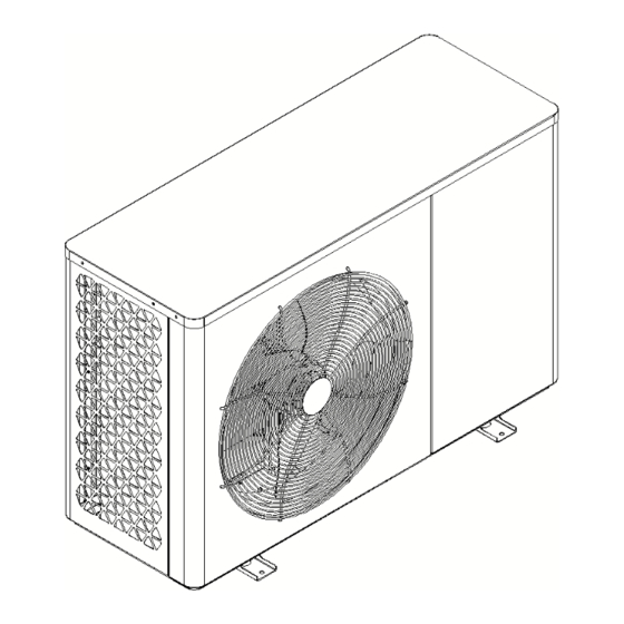
Page 17: Chapter 4 Dimensions
Chapter 4 Dimensions Model: WDLRK-10ⅠBM/A1... -
Page 18: Chapter 5 Product Parameters
Chapter 5 Product Parameters Model WDLRK-10ⅠBM/A1 WDLRK-12ⅡBM/A1 Rated heating Capacity 10 kW 11.8 kW Heating Rated Input 2.18 kW 2.59 kW Rated Heating Current 9.5 A 3.94 A 4.59 4.55 Rated Cooling Capacity 11.2 kW 13.3 kW Rated Cooling Input 3.4 kW 3.78 kW Rated Cooling Current... - Page 19 Note 1: Rated heating conditions: ambient Dry-bulb temperature 7 ℃, Wet-bulb temperature 6 ℃, inlet water temperature 30 ℃, outlet water temperature 35 ℃; Rated cooling condition: ambient Dry-bulb temperature 35 ℃, Wet-bulb temperature 24 ℃, inlet water temperature 23 ℃, outlet water temperature 18 ℃; ...
-
Page 20: Chapter 6 Electrical Wiring Diagram
Chapter 6 Electrical Wiring Diagram AC contactors must be added to the electrical devices such as circulating pump, solar water pump, lower return pump and auxiliary electric heating. - Page 23 Diagram of Diagram of Main Power Connection Single-Phase AC Three-Phase AC Main Power Cord AC Power Supply Single-Phase AC Three-Phase AC a: Field Wiring b: Cable c: Leakage Switch d: Overload Fuse Engineering signal line connection of the unit (attention should be paid to separate strong and weak current wiring)。...
-
Page 24: Chapter 7 Language Settings
Chapter 7 Language Settings 1, The device provides eight languages for selection, including English, Polish, Hungarian, Spanish, Greek, French, Italian and Chinese, which can be switched through the language setting, as follows: In the main interface, press to enter the setting menu, 2,... - Page 25 Chapter 8 Operational Manual for Wire Controller Daily Schedule Display Setting Timed On/Off Weekly Schdule Time and Date Sterilization Timer Timer Cancel Timer Wifi Setting Silent Mode User Parameters DHW Pump Manual Defrost History Error Setting Floor Dry-Up Manu Force Open I heat Force open T heat Force Hot Water Holiday Away...
-
Page 26: Main Interface
8.1 Main Interface... - Page 27 Icons Meaning Item Switch Switch on/off on/off Used to enter the query menu or Query/Retur return to the previous level Used to page up or adjust parameter Page up values Used to page down or adjust Page down parameter values Used to enter the settings menu or Set/Confirm confirm...
-
Page 28: Basic Usage
Main interface 3: (dual-zone mixing + hot water): Main interface 4 : (dual-zone water temperature + hot water): This system includes dual-zone air-conditioning water temp (zone A) + room temp control ( zone B ); This system includes dual-zone air-conditioning Zone A can be heating or cooling, while zone B can water temp control (zone A can be heating or only be heating. - Page 29 8.2.2 On/Off 8.2.2.1 Wire Controller Switches on/off Air-conditioning Area Press in the main interface, select the air-conditioning area to be turned on/off, then press the key , and press to confirm turn on/off the cooling or heating of the air-conditioning area. Take the single-zone water temperature as an example, first press the key to select the air-conditioning area, then press the key...
- Page 30 Press in the main interface, select the hot water area, then press the key , and press to turn on/off the hot water, as shown below : 8.2.3 Adjust the Temperature Press on the main interface, select the area where the temperature needs to be adjusted, and press to display the temperature adjustment box, as shown below: Then, adjust the temperature value by pressing the...
- Page 31 Press the key on the main interface to display the “Set Mode” window, as shown below: Press to select the desired mode, and then press to confirm setting. If pressed the key , the “Set Mode” window will be closed directly to cancel the current mode setting. 8.2.5 Time Setting: All time modifications (such as year, month, day, hour, minute, second) of the wire controller are operated in the same way.
- Page 32 8.3.1 Error Query Interface Press on the main interface to enter the Query interface. You can see three options: Error, Status, and Version. Use to select, and press enter the option. When there is an error, the error interface is as shown in the figure below (press to eliminate the error that meets the reset condition) →...
-
Page 33: Settings Menu
8.3.3 Version Query Interface When dealing with after-sales issues, in order to locate the problem better, it may be necessary to provide the software information of the heat pump unit, which can be viewed through the version query interface. 8.4 Setting Manu 8.4.1 Display Setting Display settings can set the needs of daily use, such as language, screen brightness, lock screen, key sound, etc., enter the display setting interface through the following path:... - Page 34 If the date and time do not correspond to the actual time, modify the date and time through the following path: Main interface > Setting menu > Date and time For time modification, please refer to the time setting operation. 8.4.3 Timer 8.4.3.1 Timed on/off 8.4.3.1.1 Regularly turn on/off every day...
- Page 35 Press to the '' MODE'' and press the key to pop up the display window. Press to adjust the setting value. If press the key , the display window will be closed without saving any changes. If press the key , the setting will be saved and the display window will be closed.
- Page 36 The specific action of the heat pump unit is described as follows: Time Action Reminder: If the start time and end time are the same, the Hot Water 1:00 start time is later than the end time, the cross day setting or the Mode On temperature exceeds the allowable range of this mode, the group 6:00...
- Page 37 Note: The timer setting operation is the same as the daily timing on/off operation. Tips: If the start time and end time are the same, the start time is later than the end time, or the setting spans across days or the temperature exceeds the allowable range of this mode, this settings will be invalid, and the following window will appear: 8.4.3.1.3 Scheduled Cancellation If you want to cancel all settings at one time (without affecting other scheduled settings), please follow...
- Page 38 8.4.3.2 Sterilization Timer There are two ways to use the Sterilization Timer: 1.Timed use; 2. Manual use. The sterilization function is used to kill bacteria and germs in the hot water tank. The temperature of the hot water tank will be forced to reach 61-70 degrees, and the sterilization temperature can be set in the advanced settings.
- Page 39 As shown, the setup will go into sterilization on Mondays and Wednesdays at 21:00. ⚫ The manual method is as follows: The priority of manual control is higher than that of timing control, press move to ''Current State''. If the Current State is ''off'', press to manually enable the sterilization function.
- Page 40 There are two groups of timers, press move to the circle box, press to use or cancel this group of timers (the used circle box will be ticked). Note: For time setting, please refer to 7.2.5 Time Setting. The Manual Silent method is as follows: The priority of manual control is higher than that of timing control, press or move to ''Current State''.
- Page 41 8.4.4 Network Configuration Guidelines The wire controller has a built-in WI-FI module, which can establish communication with the mobile APPs. Allow users to use the mobile APPs to control the unit. When configuring the wire controller to a WI-FI network for the first time, it is necessary to ensure that the wire controller and the mobile phone are under the same WI-FI signal, and the signal cannot be too weak.
- Page 42 8.4.5 User Parameters User parameters can be directly used by end users, as shown in the interface: For more user parameters, please refer to the following table (the actual parameters are subject to the display of the wire controller): Setting Range Unit Cooling Mode...
- Page 43 Sterilization Forbidden、Use ℃ Sterilization Temperature 60…70 Sterilization Cycle Max 90…300 High Temp Sterilization Time 5…60 Forbidden Low-Temp Curve1 Low-Temp Curve2 Low-Temp Curve3 Low-Temp Curve4 Low-Temp Curve5 Low-Temp Curve6 Low-Temp Curve7 Low-Temp Curve8 Zone A Cooling Curve High-Temp Curve1 High-Temp Curve2 High-Temp Curve3 High-Temp Curve4 High-Temp Curve5...
- Page 44 Low-Temp Curve8 High-Temp Curve1 High-Temp Curve2 High-Temp Curve3 High-Temp Curve4 High-Temp Curve5 High-Temp Curve6 High-Temp Curve7 High-Temp Curve8 Curve9 Forbidden Low-Temp Curve1 Low-Temp Curve2 Low-Temp Curve3 Low-Temp Curve4 Low-Temp Curve5 Low-Temp Curve6 Low-Temp Curve7 Low-Temp Curve8 Zone B Cooling Curve High-Temp Curve1 High-Temp Curve2 High-Temp Curve3...
- Page 45 Low-Temp Curve2 Low-Temp Curve3 Low-Temp Curve4 Low-Temp Curve5 Low-Temp Curve6 Low-Temp Curve7 Low-Temp Curve8 High-Temp Curve1 High-Temp Curve2 High-Temp Curve3 High-Temp Curve4 High-Temp Curve5 High-Temp Curve6 High-Temp Curve7 High-Temp Curve8 Curve9 ℃ Curve #9 - TA - Cooling 1 -5…46 ℃...
- Page 46 In the user parameter interface, select one of the "A zone cooling curve", ''A zone heating curve'', ''B zone cooling curve'', ''B zone heating curve'' as needed or multiple, press the key , disable or use a different temperature curve of ambient temperature preset by using the key or key, and press to save the modification.
- Page 47 Only when the module is in a running state and the water temperature, fin temperature, and other conditions are met can the key be pressed to successfully enter defrosting. The current state of the module will switch to being defrosted, therwise, maintain the original state. 8.4.8 History Error Errors that have occurred on the unit (including those that have been reset) will be recorded in the controller, and the query method is as follows:...
- Page 48 8.4.9 Floor Dry-Up This function can only be enabled when the ''floor heating water temp probe'' is in use and the unit is in standby mode. Find “Main interface” > “Setting menu” > “Floor Dry Up” Press the key to display the confirmation window (as shown), press again to confirm the use of this function and close the window.
- Page 49 Press the key to display a confirmation window (as shown below), press the key to confirm the use of this function and close the window, press the key to cancel and close the window. If the auxiliary electric heating function has been turned on, press the key in the option of "force open I heat", and a confirmation window (as shown) will appear.
- Page 50 When there is a cooling or heating demand and the heat pump is in cooling or heating mode, there may be still a demand for hot water. The electric heating function of the “Force open T heat” can be used for hot water production.
- Page 51 The forced hot water mode function forces the system to operate in the hot water production mode, and the heat pump and auxiliary electric heating, water tank electric heating, and external heat source will all operate in the forced hot water mode. Press on the key in the main interface to enter the settings menu, and press to find the...
- Page 52 In heating or hot water mode, heat can be provided by manually forcing an additional heat source on. Follow the following path to find the function of "Force AHS": ''Main interface'' > ''Settings menu'' > '' Force AHS''. Press to display the confirmation window, press to confirm the opening of the force AHS and close the window.
- Page 53 The Holiday Away mode is often used to go out during winter holidays to prevent waterways from freezing. Enter this mode after leaving home and end it before returning home. Press the key in the main interface to enter the settings menu, and press to find 'Holiday Mode Set'.
- Page 54 The setting is as follows: Press move to 'Function use', press to set to 'Use' (press again to disable), use the holiday away function → press move to ' Mode Heat Use', press to set to 'Use'. The settings for domestic hot water use and sterilization use are the same as heating mode use . 8.4.14.2 Holiday Home Mode Holiday Home Mode is similar to Timing Mode.
- Page 55 8.4.15 Advanced Setting For installation and service needs, authorized engineers or service personnel can modify the parameters of the controller through the following path and enter passwords. The path to the advanced settings interface is as follows: “Main interface'' > ''Settings menu'' > ''Advanced settings'', enter the correct password in the following interface and press the key to confirm.
- Page 56 8.4.15.2 Smart Grid Enter the password of high-level permission when entering advanced settings, so as to obtain the setting permission of smart grid function. After entering the password in 'Advanced Settings', entering' Parameter Configuration' will display multiple parameter groups. move to 'System Parameters' and select' Smart Grid'. If the 'Smart Grid' is disabled, press to change to 'on’.
-
Page 57: Chapter 9 Network Configuration Instruction
Chapter 9 Network Configuration Instruction 9.1 Download the “Huilian Smart” APP Download the "Huilian Smart" APP by scanning the QR code on your mobile phone, complete the registration and login, and allow all access rights of this application to get the best user experience. 9.2 Connecting Wi-Fi Ensure that the mobile phone is under the same Wi-Fi as the device to be connected, select the 2.4 GHz Wi-Fi network on the mobile phone and enter the password to connect the mobile phone to Wi-Fi. - Page 58 4. After the renaming is completed, both Wi-Fi names, "xxx-2. 4G" and "xxx-5G", can be found on the Wi-Fi search page of the mobile phone. 9.3 Add Device 1) Turn on the Wi-Fi and Bluetooth of the mobile phone and enable location access. Please ensure that both Wi-Fi and Bluetooth are turned on;...
- Page 59 4、 Wait for a moment, when 3、 Enter the WI-FI account 1. Wait for a moment, select progress number and password of the device to be added, finished, press the "Finish" 2、Press the "+" icon on mobile phone and press the "Add" the right;...
- Page 60 Scan the device network Enter the Wi-Fi account Press on the "Scan" icon in QR code. After number and password of Check the 'WI-FI Status the upper right scanning, as shown in the mobile phone Confirmed' and press on' corner; the window above, connection, and press the Next 'icon;...
- Page 61 Wait for a moment. When the progress bar is finished, After the search is press the “Done” icon in Searching for the device. completed, press the the upper right corner to "+" icon on the right complete the device addition 9.4 Complete the Spatial Information 1) Enter the "Huilian Smart"...
- Page 62 Fill in the space information, Press on the 'Me' icon in the Press on the "Space Press on the 'My Space' and then press the "Save" bottom right corner Management" icon; icon; icon in the upper right corner; Press on the "Add Member" Select the invitation Press on 'View Space' Fill in member information;...
- Page 63 After role setting, press the Press on the "Space Role" 'Save' icon in the upper icon; right corner. 9.5 Share Device After entering the device panel, press the "Modify" icon key in the upper right corner to enter the device details interface.
- Page 64 4、 Select the sharing method to 1、 Press the "Modify" icon 2、 Press on the 'Share 3、 Press on the "Add fill in the account, and press in the upper right Device' icon; Sharing" icon below; the 'Finish' icon to complete corner;...
- Page 65 Status Query Interface (main More menu (main interface - Setting Mode Menu (main main interface interface - more - More) interface - Mode) advanced - status query) History Error Interface (main Language setting interface interface - more - Parameter Settings Interface (main interface - more - advanced - history setting - language)
-
Page 66: Chapter 10 Units Cascading Operation Instructions
Chapter 10 Units Cascading Instructions... - Page 67 Cascading Units Installation Instructions: The above diagram shows the wiring diagram of 16 (maximum) modular units cascading. The steps for cascading modules are as follows: Step 1: Power off all units; Step 2. Corresponding wiring of the cascading interface; As shown, the terminal of controller J2 is a module cascading terminal.
- Page 68 Chapter 11 Common Errors and Solving Methods Errors Reset Detection Conditions Alarm Action Solutions Device Errors Insufficient 30s after the water pump is Stop the unit, stop Check whether water flow started, it starts to detect insufficient the air conditioning its corresponding water flow;...
- Page 69 The high Check high pressure of the pressure PRSd pressure sensor is too high The compressor After the compressor is running Shut down the Check whether is under low pressure [low pressure detection delay], or compressor the input status of protection when [standby detection low pressure] the compressor low...
- Page 70 The outlet water Detection during cooling: Shut down the Check the outlet temperature of the When the plate heat exchanger compressor water temperature plate heat exchanger outlet water temperature “non TWout1 and the is too low TWout1≤[cooling outlet water frequency-down return water temperature is too low], alarm;...
- Page 71 When the plate heat exchanger outlet water temperature TWout1<[heating outlet water temperature is too high]-[temperature difference when exiting the heating outlet water temperature protection is too high], reset is allowed. The return Detection during heating: water temperature When the return water of plate heat temperature of the plate heat exchanger is too high...
- Page 72 between the outlet and return of the plate heat exchanger is less than [excessive temperature difference between outlet and return water] -5, automatic reset is allowed. Detection during compressor on Shut down the Check the temperature and non-defrosting operation: compressor temperature probe difference between When the temperature difference...
- Page 73 【cooling suction too low】+2, reset is allowed; The speed of fan This error is only detected when Shut down the Check whether 1 is abnormal; the Variable Frequency Fan Setting is compressor the PWM fan wiring The speed of fan PWM fan;...
- Page 74 temperature (or the temperature behind the valve) > [cooling evaporating too low] + 2, reset is allowed; Low ambient When the compressor is in the Shut down the Check whether temperature limits ambient temperature shutdown zone, compressor the ambient the opening of the an alarm will sound.
- Page 75 Hot water tank Shut down the temperature error compressor Total outlet Shut down the water temperature compressor error Total outlet Shut down the AHS water temperature error of the system Floor heating Shut down the water inlet compressor temperature error Outlet water Shut down the temperature error of...
- Page 76 After the errors are eliminated, the error can only be reset by powering on again; Errors requiring power-on reset: please check the error table. 2) Limited automatic reset (A/M) After the error alarm is triggered, when the error is eliminated, a delay of [error reset time] will occur. Within this time, when the same error no longer occurs, it will automatically reset;...
-
Page 77: Chapter 12 Installation Requirements For Device Water System
Chapter 12 Installation Requirements for Water System ◼ The installation should be carried out according to the engineering installation diagram and corresponding construction standards; ◼ The drain pipe of the water tank should be installed near the drainage ditch and the drain outlet as much as possible to facilitate drainage;... -
Page 78: Chapter 13 Commissioning And Trial Run
Chapter 13 Commissioning and Trial Run ◆ Preparations before trial run Check whether there is any abnormality in the device (whether the pipeline system in the device is damaged, whether the fan blades rotate well and do not interfere with other components); ... - Page 79 Chapter 14 Site Requirements for Heat Pump Installation The Master Unit The air source heat pump should be installed in a large space with good ventilation; The installation location should ensure that the air inlet and outlet are unobstructed; ...
- Page 80 Installation Mode (mm) (mm) (mm) (mm) (mm) (mm) Single unit installation ≥20 ≥50 ≥50 ≥50 ≥10...
- Page 81 Cascade Installation ≥20 ≥50 ≥50 ≥50 ≥10 ≥10...
- Page 82 Please ensure that the device is in a horizontal state during installation! M10 Nut M10 Spring Washer M10 Flat Washer The Heat Pump Rubber Damping Blocks Expansion Bolt Base...
-
Page 83: Chapter 15 Maintenance
Chapter 15 Maintenance ◼ Air source heat pumps are highly automated equipment that requires regular status checks during use. If long-term and effective maintenance can be carried out from time to time, the reliability and service life of the device will be improved. ◼... - Page 84 ◼ To clean the condenser of the main machine, our company recommends using citric acid solution with a concentration of 5% at 50 ℃ - 60 ℃. Start the built-in circulating pump of the main machine to clean for 2 hours, and finally rinse it 3 times with tap water.(It is recommended to reserve a three-way connection when installing the pipeline, and seal one connection with a gate valve or plug to prepare for connection during cleaning.)It is forbidden to clean the condenser with corrosive cleaning fluid.
-
Page 85: Chapter 16 Scenario Diagram
Chapter 16 Scenario Diagram... -
Page 86: Appendix
Appendix ⚫ Installation and Configuration of Power Cords. ⚫ The power cord connected to the main unit must use wires that comply with local regulations and be fastened with wire fixing devices. Improper connection or fastening will cause fire, etc. ⚫... - Page 87 QC Card...
-
Page 88: Packlist
Packlist Seq. Items Qty. (unit) Remark Heat Pump Wire Controller Connection Wire 5 meters Y Shaped Filter 60-mesh filter screen Temperature Sensor 6 meters Rubber Damping Blocks QC Card included in the manual Packlist included in the manual Manuel Instruction AMA-SMS-348...
Need help?
Do you have a question about the WDLRK-10 I BM/A1 and is the answer not in the manual?
Questions and answers