
Related Manuals for Dolphin MXP908

Summary of Contents for Dolphin MXP908
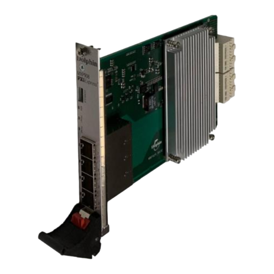
- Page 1 PXIe x8 NTB Cable Module MXP908 MXP908 - PXIe PCIe x8 Gen4 NTB Peripheral Module Users Guide Version 1.1 Date: 9 December 2023 MXP908 PXIe NTB module User’s Guide – Dolphin Interconnect Solutions Page 1...
- Page 2 MXP908 PXIe NTB module User’s Guide – Dolphin Interconnect Solutions Page 2...
-
Page 3: Table Of Contents
E MODULE ...................................15 UPPORT TECHNICAL INFORMATION ............................15 ..............................15 OARD REVISION HISTORY ............................15 ABLE APPING COMPLIANCE AND REGULATORY TESTING .........................16 LIMITED WARRANTY..............................17 ..............................17 ARRANTY ERIOD .................................17 OVERAGE ..............................17 ERVICE ROCEDURE MXP908 PXIe NTB module User’s Guide – Dolphin Interconnect Solutions Page 3... -
Page 4: Disclaimer
THE PRODUCT BY THE PURCHASER. PCI Express External Cabling specification 4.0 is, as of the release of MXP908 PXIe module, not completed and ratified by the PCI- SIG. The MXP908 PXIe x8 cable module is designed to the new specification, but Dolphin cannot guarantee the card will be compliant to the final 3.0 version. -
Page 5: Terms And Acronyms
Port PCIe Cable port. The MXP908 PXIe module has four x4 ports, named P1, P2, P3, P4. Ports P1 and P2 can be merged to one x8 port. Ports P3 and P4 are unused. The physical ports are identified by text on the PCIe brackets. -
Page 6: Mxp908 Pxie Module High Level Specification
AOC data sheet for details. Please consult the AOC data sheet for details. NOTE: The MXP908 module link LEDs will start flashing yellow when a PCIe switch temperature of 95°C (203°F) is reached or when the AOC reports a temperature 5°C (41°F) lower than the max operating temperature. -
Page 7: Airflow - Operating Environment
Cable Connections The MXP908 module is designed to support both long and short PCIe copper cables as well as PCIe active optical cables (AOC). The MXP924 cable ports are compliant to the SFF-8644 industry specification and supports PCIe cables compliant to the PCIe External Cabling Specification 4.0. -
Page 8: Installation
Connecting the Cable Please carefully install the cable connector into the connector housing on the MXP908 module. Cable port 1 is located at the top of the face plate bracket. To install the cable, match the cable house with the connector on the MXP908 module. Use even pressure to insert the connector until it is secure. -
Page 9: Disconnecting The Cable
Step 7 - Verify Installation & LEDs The MXP908 PXIe module comes with 4 RGB LEDs which show the corresponding cable port status according to Table 2: LED below. The LEDs are visible through cut-outs in the front panel below each port. -
Page 10: Operation
Operation Configuration and DIP Switches The MXP908 module has two banks of 8 DIP switches. The default factory setting for the MXP908 module is NTB Host mode, single (up to x8) link connection. The MXP908 module has DIP switches for setting special modes or operations, the meaning of each DIP switch depends on the loaded firmware. - Page 11 DIP switch Settings The following DIP SW1 Switch settings should be considered when configuring the MXP908 PXIe module for NTB operation: Config Use Case MXP908 SW1 DIP SW1 view – 256MB BAR 32GB BAR Option DIP settings All systems may not support this.
-
Page 12: Use Cases
Use Cases The MXP908 module may be used to connect a PXIe chassis to one or more PXIe chassis having a MXP908 installed or standard PCs having a MXH914, MXH918 or MXH930 installed. The DIP switch settings are summarized in section Configuration and DIP Switches on page 10. -
Page 13: Use Case C - Mxs924 Switch Configurations - Ntb Mode
The MXP908 module can be combined with the MXS924 24 port PCIe switch to create larger PCIe networks. Each node typically has a Dolphin MXH9xx or MXP908 NTB adapters and a x4, x8 cable connection to the MXS924 switch. All adapter cards operate in NTB mode. -
Page 14: Firmware Upgrade
Identifying the PXIe module The module has a label-sticker with the serial number in the format ‘MXP908-YY-ZZZZZZ’, where YY denotes the revision (e.g. CC) and ZZZZZZ denotes the serialized production number (e.g. 012345) – this whole string makes up the serial number of the module (i.e. -
Page 15: Support
Initial version for testing. Not available • MXP908-CD Production version PCIe Cable Port Mapping The MXP908 module has a quad SFF-8644 connector. Only P1 and P2 are connected. MXP908 PXIe NTB module User’s Guide – Dolphin Interconnect Solutions Page 15... -
Page 16: Compliance And Regulatory Testing
This equipment is tested to comply with the limits for a Class A digital device, pursuant to part 15 of the FCC Rules. RoHS Compliance The MXP908 module is RoHS compliant. A Compliance certificate issued by the manufacturer is available upon request. -
Page 17: Limited Warranty
Dolphin Interconnect Solutions warrants this product to be free from manufacturing defects under the following terms: Warranty Period Dolphin warrants the product for one (1) year from the date of purchase. Extended warranties are available for purchase. Coverage To the extent permitted by applicable law, this warranty does not apply to: •...
Need help?
Do you have a question about the MXP908 and is the answer not in the manual?
Questions and answers