
Subscribe to Our Youtube Channel
Summary of Contents for Flash Technology FTC 370
- Page 1 ADLS Lighting Control Module User Manual Document Number F7911500 Flash Technology, 332 Nichol Mill Lane, Franklin, TN 37067 flashtechnology.com 1.615.503.2000 | 1.800.821.5825...
-
Page 2: Front Matter
While every effort has been made to ensure that the information in this manual is complete, accurate and up-to- date, Flash Technology assumes no liability for damages resulting from any errors or omissions in this manual, or from the use of the information contained herein. Flash Technology reserves the right to revise this manual without obligation to notify any person or organization of the revision. - Page 3 FTC 370 / 370A LCM USER MANUAL AVOID TOUCHING LIVE CIRCUITS Avoid touching any component or any part of the circuitry while the equipment is operating. Do not change components or make adjustments inside the equipment with power on. DO NOT DEPEND ON INTERLOCKS Never depend on interlocks alone to remove unsafe voltages.
-
Page 4: Table Of Contents
2.5.1 Power Up ..............................18 2.5.2 Check Alarm Status ............................ 19 2.5.3 Check Monitoring Status ..........................19 Section 3 – FTC 370 LCM Operation ..........................19 3.1 System Overview ............................... 19 3.2 IP Address & MAC ID ............................20 3.3 LCM MODBUS MAP ............................20 Section 4 –... -
Page 5: List Of Figures
5.2 Ordering Parts ............................... 27 5.3 RMA Policy ..............................27 LIST OF FIGURES Figure 1-1 – FTC 370 and OVP (optional) installation overview ..................7 Figure 1-2 – External Enclosure ............................. 8 Figure 1-3 – FTC 370 Component Locations ........................8 Figure 1-4 –... - Page 6 FTC 370 / 370A LCM USER MANUAL Table 4-4 – Troubleshooting – Cannot Communicate to the LCM over Ethernet ............25 Table 4-5 – Troubleshooting – Cannot Control the Lights Using Modbus ..............26 Table 5-1 – Optional Parts ............................27 Table 5-2 –...
-
Page 7: Section 1 - Overview
Aircraft Detection Lighting System (ADLS) utilizing standard Modbus TCP protocol. The FTC 370A version provides the additional capability for a SCADA or other control system to monitor alarms in addition to the ADLS. The FTC 370 is currently compatible with the Detect Harrier and the Terma Scanter ADLS systems. -
Page 8: Lcm Component Identification
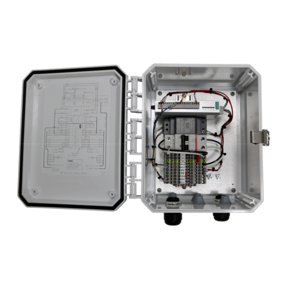
FTC 370 / 370A LCM USER MANUAL 1.2 LCM COMPONENT IDENTIFICATION Figure 1-2 – External Enclosure Ethernet I/O Module Industrial Power Supply 30 W 15 V DIN Rail Harness 2 FTC 370 Harness 1 FTC 370 TB1 Term Block CB ASSY FTC 370 Figure 1-3 –... -
Page 9: Figure 1-4 - Ftc 370A Component Locations
FTC 370 / 370A LCM USER MANUAL Ethernet I/O PCB FTC 370 LCM Module Industrial Relay Harness 2 Power Supply FTC 370 30 W 15 V Din Rail Harness FTC 370A Harness 1 FTC 370 TB1 Term Block FTC 370A Figure 1-4 –... -
Page 10: Section 2 - Installation
2.2 MOUNT THE FTC 370 LCM Locate the FTC 370 LCM in an area that will allow proper access to the enclosure. Ensure the mounting location does not interfere with the quick-release latch that secures the enclosure’s door. Release the latch to open the door for internal access. -
Page 11: Figure 1-5 - Ac Line Ac Line Termination
FTC 370 / 370A LCM USER MANUAL Wire Color Function Wiring Connections External Connections (120 VAC) or Black Input Power TB1 – BLK (240 VAC) - L1 (120 VAC) or White Input Power TB1 – WHT (240 VAC) – L2... -
Page 12: Figure 1-6 - Fh #1 Cable Termination
FTC 370 / 370A LCM USER MANUAL Figure 1-6 – FH #1 Cable Termination Figure 1-7 – Cable Entry from Bottom of Control Box ©2023 Flash Technology, LLC Revision A – 6/26/2023... -
Page 13: Figure 1-8 - Fh #2 Cable Termination
FTC 370 / 370A LCM USER MANUAL Figure 1-8 – FH #2 Cable Termination Figure 1-9 – JUMPER REMOVAL IF TWO BEACONS ARE CONNECTED, REMOVE JUMPER BETWEEN RED2 AND ORG ©2023 Flash Technology, LLC Revision A – 6/26/2023... -
Page 14: Wiring The Lcm With Ovp System
2.4 WIRING THE LCM WITH OVP SYSTEM The LCM can be installed in conjunction with the optional Flash Technology Overvoltage Protection System (OVP- Radar, Part number 1390191). Install the OVP in between the LCM and each Beacon. See OVP manual for installation. -
Page 15: Figure 2-2 - Ftc 370 Lcm Enclosure Mounting And Outline
(273.05) 9.36 (237.74) FRONT VIEW RIGHT SIDE VIEW KNOCKOUT TABLE 7.01 LETTER KNOCKOUT SIZE DIA (178.05) 0.875 (22.4) 1.093 (27.8) BOTTOM VIEW Figure 2-2 – FTC 370 LCM Enclosure Mounting and Outline ©2023 Flash Technology, LLC Revision A – 6/26/2023... -
Page 16: Figure 2-3 - Ftc 370 Lcm Internal Wiring Diagram
FTC 370 / 370A LCM USER MANUAL Figure 2-3 – FTC 370 LCM Internal Wiring Diagram ©2023 Flash Technology, LLC Revision A – 6/26/2023... -
Page 17: Figure 2-4 - Ftc 370A Lcm Internal Wiring Diagram
FTC 370 / 370A LCM USER MANUAL Figure 2-4 – FTC 370A LCM Internal Wiring Diagram ©2023 Flash Technology, LLC Revision A – 6/26/2023... -
Page 18: Verifying Operation
FTC 370 / 370A LCM USER MANUAL 2.5 VERIFYING OPERATION Apply power to the LCM and verify operation. 2.5.1 POWER UP Power the system using the breaker located on the TB1 Terminal Block. Observe that the LEDs on the power supply and MOXA are illuminated. -
Page 19: Check Alarm Status
FTC 370 / 370A LCM USER MANUAL State Description Power Amber System power is ON System power is OFF Ready Green System is ready Flashing Flashes every 1 second when the “Locate” function is triggered Flashing Flashes every 0.5 second when the firmware is being upgraded Flashing ON/OFF cycle period of 0.5 second represents “Safe Mode”... -
Page 20: Ip Address & Mac Id
Information Label on the enclosure door for unit specific information. Figure 3-1 – LCM Information Label 3.3 LCM MODBUS MAP Flash Technology utilizes two registers in the Moxa E1213 Modbus map accessed via the Ethernet on the LCM. Parameter Name Description... - Page 21 FTC 370 / 370A LCM USER MANUAL the light to turn ON. Please note: when not suppressed, the light will follow normal operation and turn the light ON if the photodiode determines it is nighttime. So, if the DO command is not sent and daylight conditions are detected by the photodiode, the light will remain off but is functioning correctly.
-
Page 22: Table 3-2 - Complete Modbus Address And Register Map (I/O)
FTC 370 / 370A LCM USER MANUAL DO_pulseOffWidth unit: 1 ms 0068 03:HOLDI 40069 word REGISTER DO_pulseOnWidth unit: 1 ms 0052 03:HOLDI 40053 word REGISTER DO_pulseStatus 0: STOP, 1: 0016 01:COIL 00017 START STATUS DO_status 0: OFF, 1: ON 0000... -
Page 23: Section 4 - Maintenance And Troubleshooting
4.1 MAINTENANCE No regularly scheduled maintenance is required for the LCM. • Flash Technology warranties the function of the LCM to meet or exceed FAA/ICAO requirements for a 5-year period. • Optional mounting brackets and cable glands should be checked periodically for tightness. -
Page 24: Table 4-1 - Troubleshooting - Lcm Does Not Turn On
FTC 370 / 370A LCM USER MANUAL Possible Cause Action AC Mains power failure / AC Power not applied Check AC mains power using multi-meter; Restore Power. External circuit breaker OFF/Tripped Check circuit breaker; Move breaker to ON position. Internal circuit breaker OFF/Tripped Check circuit breaker;... -
Page 25: Table 4-3 - Troubleshooting - Beacon Alarm, False Alarm Or No Alarm
FTC 370 / 370A LCM USER MANUAL Possible Cause Action Incorrect / No dry contact wiring Inspect for correct alarm connections: normally open (NO) contacts close on alarm, normally closed (NC) contacts open on alarm Jumper missing between RED2 and ORG on TB1... -
Page 26: Lcm Repair Procedures
Note: While performing the following steps, check for any loose connections and other damaged components. 4.3.1 REPLACE THE LCM FTC 370 LCM Part Number: F1371500, FTC 370A LCM Part Number: F1371510 LCM REMOVAL Disconnect the LCM’s cable pigtail from the power source and any monitoring equipment. Unfasten the hardware that holds the LCM unit to the structure or mounting bracket. -
Page 27: Ordering Parts
* PARTS FOR THE FTC 370A LCM ONLY Table 5-2 – Spare/Replacement Parts 5.3 RMA POLICY If any system or part(s) purchased from Flash Technology needs to be returned for any reason (subject to the warranty policy), please see the current RMA policy available online at flashtechnology.com/rma ©2023 Flash Technology, LLC...
Need help?
Do you have a question about the FTC 370 and is the answer not in the manual?
Questions and answers