Table of Contents

Related Manuals for Mono ALPHA DEPOSITOR

Summary of Contents for Mono ALPHA DEPOSITOR
- Page 1 Store this document safely and ensure it is available at all times. MANUAL No.Y-AL-01E Non-availability may affect the service / repair of your machine. CONTROLLER OPERATION MANUAL for the ALPHA DEPOSITOR (Programming Instructions)
-
Page 2: Table Of Contents
INDEX INTRODUCTION page 6 USE OF KEY PAD -- Key functions page 9 USE OF MENU SCREENS page 13 A) The creation and editing of product programs 1. Drop deposit menu …………………………………………….page 13 • Quantity • Deposit speed • Rotory speed •... - Page 3 B) Memory facilities 1. Memory menu………………………………………………page 23 • Save • Save new program • DELETE item • Sort • DELETE directory 2. Product select……………………………………………..page 26 • Existing programs • New drop products • New strip products • Other new products 3.
- Page 4 3. Set-up and diagnostics…………………………….….page 30 • Set time • Set date • Test DACS menu • Keypad test • Inputs test • Exit to operating system • Loading new program 4.Initial checks…………………………………………….page 34 5. Field set-up……………………………………………...page 35 • Amplifier replacement •...
-
Page 5: Introduction
1.0 INTRODUCTION This manual covers all functional aspects of the ALPHA depositor that can only be addressed through data entry into the electronic controller situated on its control pod. Such aspects include product creation, product program storage into memory and retrieval, program deletion, machine set-up and diagnostics display. - Page 8 - 8 - FG 077 – 08-05 RAC...
-
Page 9: Use Of Key Pad -- Key Functions
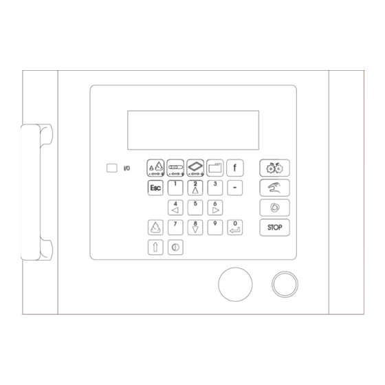
2.0 USE OF KEYPAD Fig 2. Shows the ALPHA’s controller keypad and LCD screen. The five keys immediately below the controller’s LCD screen are menu option keys. Selecting these will gain the user access to the relevant menus. Data entry into the controller is by use of the directional / numerical keys (G), - key (R), and enter key . - Page 10 DESCRIPTION OF CONTROL PANEL - KEY FUNCTIONS DRG REF. FUNCTION DESCRIPTION PRIME This button activates the hopper pump for as long as it is pressed, providing either a product creation or run menu are on screen, and all safety guards are properly closed. It fulfils two functions: - a.To prime the hopper pump and nozzles with product mix.
- Page 11 START BUTTON Pressed once will power up controller screen. Pressed a second time will activate all power electric circuits. All machine facilities can be used once pressed provided all safety guards are properly closed and emergency stop button is released. EMERGENCY STOP Immediately isolates all power circuits.
- Page 12 STRIP PRODUCT MENU Selects screen menu for creation of strip products i.e. products with length. TRAY MENU Selects screen menu to enter values for positioning of product on tray. FILE MENU Selects screen menu to save, retrieve and delete programs. FUNCTION MENU Selects screen menu to enter edit/create menu and machine set-up menus.
-
Page 13: Use Of Menu Screens
Upon switching on of the ALPHA depositor by means of the start button (E), the controller LCD screen will be displaying the program selection menu. To edit a program or simply run a program, selection must be made be means of the up and down arrow keys and entered. -
Page 14: Quantity
• QUANTITY Enter a positive numerical reading to achieve rotation of the deposit pump and a quantity of product mix extruded through the selected template assembly. The entered value is proportional to the amount of pump rotation but is, by necessity, uncalibrated in product mix quantity terms as any attempt to do so would be inaccurate should the template arrangement, product mix or pumping speed change. -
Page 15: Strip Deposit Menu
2. STRIP DEPOSIT MENU A Strip product is a product that is considered to have length e.g. the tray will continue to move while depositing. For creation of a new strip product simply press the strip deposit. menu key upon switching on the machine. The creation of a strip product consists of three separate steps, an initial deposit, a strip deposit and a final deposit. -
Page 16: Final Deposit
• FINAL DEPOSIT The entered value will produce a single drop deposit at the end of the desired strip product. By means of increasing or decreasing this value the shape of the product end can be varied. To increase the amount deposited move the cursor onto the value using the up and down arrow keys as appropriate, and enter a new value whilst holding down the shift key. -
Page 17: Per Tray
• NO PER TRAY The number of repeated rows of deposited product required along the tray’s length. NOTE - this value does not correspond to the number of products deposited across the tray, i.e. the number of nozzles on the template in use. •... -
Page 18: Set Height
• SET HEIGHT The value entered here is a reminder value. The table height adjustment handle should be set to this height. NOTE - The table height adjustment is a manual adjustment and therefore not being controlled by the controller. Care must be taken to set the table to the correct height before commencing operation of the machine, to prevent any damage being done to the tray’s being used. -
Page 19: Edit/Create Menu
4. EDIT/CREATE MENU The third product creation screen is the edit/create screen. This screen is used for the creation of slightly more complicated products that would not be possible to create in the drop or strip product menus. With this screen consideration needs to be given to the product program. The product program is the sequence of events and command instructions, imparted via the controller and the user written program necessary to describe the simultaneous and related movements of the ALPHA’s two axes to deposit one product row only. -
Page 20: Deposit Pump (Axis 0)
• MOVE A Move command will instruct each of the motors associated with the axes to start to move and to finish simultaneously. By appropriate programming each axis’s motor may also be made to remain stationary. The table drive can even be made to move in reverse to its normal forward movement when carrying out its move command. - Page 21 • SPEED The speed command sets maximum speed values, up to preset maximum values, to each of the motors linked to the ALPHA’S 3 axes during the product creation sequence of movements only, not prior, in between or after each of the deposited rows on a tray. The SPEED command is inserted into the product program just prior to the MOVE command that it is to ‘speed’...
- Page 22 • WAIT The WAIT command allows the introduction of a period of inactivity (i.e. no movement) at any point during the product creation program. The command, allowing WAIT periods in increments of 1 second, can be used to allow the complete depositing of mix before continuation onto the next deposit.
- Page 23 MEMORY FACILITIES 1. MEMORY MENU Access to the controller’s memory facilities is via the ALPHA’S file menu key (P). Within this menu the ALPHA’S memory will allow you to do the following: - • SAVE • SAVE NEW PROGRAM • DELETE ITEM •...
- Page 24 • SAVE NEW PROGRAM Enables the addition of a new product program (item) to the controller’s existing directory. Select SAVE NEW PROGRAM by using the up and down arrow keys and then pressing enter. This will reveal the prompt ‘Program name. Using the up and down arrow keys scroll through the alphabet to select the first letter of the program name to be used.
- Page 25 • DELETE ITEM Enables selected product programs to be deleted from the product program directory. This operation is also password protected to avoid misuse and mistakes. Select DELETE ITEM by using the up and down arrow keys, and then press enter. This will reveal the instruction’...
- Page 26 • SORT Enables the list of product programs to be sorted into alphabetical order if so desired. Select SORT by using the up and down arrow keys and then pressing enter to reveal another screen offering the choice of either accepting or refusing the option. Press the appropriate left or right arrow key to accept or prevent the procedure.
- Page 27 • NEW DROP PRODUCTS To create a new drop product program, access directly into the relevant menu can be selected by pressing the ‘DROP MENU’ key. • NEW STRIP PRODUCTS To create a new strip product program, access directly to the relevant menu can be selected by pressing the ‘STRIP MENU’...
- Page 28 DIAGNOSTICS AND MACHINE SET- UP SPEED SET UP MENU Enables default values for maximum speed of each of the ALPHA’S axes and acceleration values to be entered. In the absence of any other speed instruction, within the product program, the speed values entered within this menu will be used by the controller to produce machine movements.
- Page 29 The parameters contained within the ‘Speed set-up menu’ have the following effect: - • DEPOSIT SPEED Sets the maximum linear speed value (up to a maximum preset value) for the forward direction of the Deposit pump axis (Axis 0). For the depositing of product mix to make products in the absence of an alternative value entered in a SPEED command in the product program.
- Page 30 OFFSET MENU • SOFT DOUGH The distance, in millimetres, that the tray is progressed forward, beyond the point at which the tray is detected by the tray sensor to correctly position the tray underneath the soft dough hopper depositing centre line. Once progressed forward by the offset distance, the tray is in the correct position for use with the information entered under ‘tray length’.
- Page 31 TEST DACS MENU (digital to analogue converters) Enables a controller hardware test. Only to be performed by, or on the instructions of MONO Equipment. IMPORTANT: - DISABLE THE MOTOR DRIVES USING THE EMERGENCY STOP BEFORE RUNNING THIS TEST Select ‘TEST DAC MENU’ by means of the arrow keys. Enter numerical values as appropriate using the main keypad to select the expected test result from on screen options.
- Page 32 • INPUTS TEST Enables readout from the LCD screen display as to the on/off status of all sensors, safety switches and power switches associated with the ALPHA giving, at a glance, confirmation of individual sensor failure or otherwise. Correct functioning of any sensor/switch will indicate a change in the display each time it changes state (i.e.
- Page 33 • LOADING NEW PROGRAM Equipment required: Interface lead (2 x 9-way D-type connector – one male, one female) approx 2M long. 386 (min) PC c/w floppy disk drive 9-way D-type serial port software- MS-DOS 4.1 or higher PROCEDURE a) At this point remove rear cover to controller pod of the ALPHA and plug in the interface lead into the 9-way D-type socket of the controller.
- Page 34 INITIAL CHECKS a. Switch machine on at mains. b. Check all safety guards are closed and emergency stop button is released. c. With zero speed command and the drive disabled, apply power to the amplifier units by pressing start button – check that 3 status LED`s are showing: - RED=OFF YELLOW=ON GREEN=OFF...
- Page 35 FIELD SET UP • Amplifier replacement Caution Extreme care must be exercised when applying these procedures to machine mounted motors to avoid incurring damage to the machine, drive and/or motor. If at all possible the initial set-up should be performed with the motor decoupled from the machine and/or drive components.
- Page 36 20 seconds • to save all changes, switch off the power and wait for the screen to power down (blank screen) and switch back on. SETTINGS REQUIRED FOR MONO ALPHA P-02 0 (0Hz) MINIMUM SPEED P-03 0.1s ACCEL RAMP TIME P-04 0.1s...
- Page 37 • INVERTER UNIT (ROTARY HEAD) IMO JAGUAR ONLY Before replacing or connecting up the inverter the following has to be done. 1: Remove link that is fitted between terminal FWD-CM. 2: Disconnect keypad potentiometer at CN2 connector; otherwise the inverter may be damaged.
- Page 38 PASSWORD SETUP SCREEN (password required) The ALPHA allows user editable password entry via a dedicated password menu (itself password protected). To gain access to the password menu first gain access to the function screen and select ‘Password’. Upon entry of the password, the password menu is invoked, and the password codes for the following menus can be entered: - Save product menu *****...
- Page 39 CONVERSION FROM OPTIDRIVE TO ALTIVAR 11 INVERTER ON OMEGA AND ALPHA DEPOSITORS OPTIDRIVE 9 10 ALTIVAR 11 9 10 ALTIVAR 11 SETTINGS 50Hz 0.1s - ACCEL RAMP TIME 0.1s - DECEL RAMP TIME LOW SPEED 2.1amp MOTOR CURRENT - 10v - ANALOG INPUT SCALE FLG - 95% FREQUENCY LOOP GAIN...
- Page 40 - 40 - FG 077 08-05 RAC...
- Page 41 4.0 ALPHA DEPOSITOR NOZZLE IDENTIFICATION RECORD SHEET - 41 - FG 077 08-05 RAC...
- Page 42 MONO Equipment Queensway Swansea Industrial Estate Swansea SA5 4EB UK Tel. 01792 561234 Fax. 01792 561016 As it is our policy to improve our machines continuously, we reserve the right to change specifications without prior notice. - 42 - FG 077 08-05 RAC...
Need help?
Do you have a question about the ALPHA DEPOSITOR and is the answer not in the manual?
Questions and answers