Advertisement
Quick Links
Advertisement

Related Manuals for ANYHZ FST-501-0R7ST2

Summary of Contents for ANYHZ FST-501-0R7ST2
- Page 1 FST-501-0R7ST2 Mini Frequency Inverter User Manual Preface...
- Page 3 General Manual of FST-501Mini Frequency Inverter In order to give full play to the functions of The frequency inverter and ensure the safety of users, please read this operation manual carefully. When you find difficult problems during use, please contact the distributors in various regions or our technical personnel, and our professionals will be happy to serve you.
-
Page 4: Display Interface
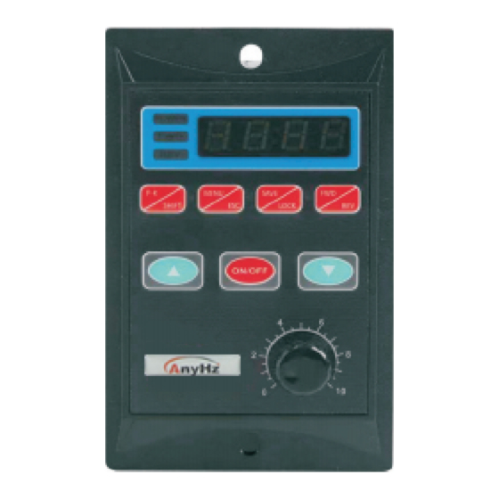
General Manual of FST-501Mini Frequency Inverter 1. Display interface POWER LED POL4 Digital display window WER LED FWD LE REV LED logo... -
Page 5: Display Interface Description
General Manual of F S T - 5 0 1 Mini Frequency Inverter 1.1. Display Interface Description: L1: POWER indicator light, power indicator light, always on. L1-1 :It is always on when the operation panel is locked, it is off when it is unlocked, and it flickers when it is under communication control. - Page 6 General Manual of F S T - 5 0 1 Mini Frequency Inverter 2. Function descriptio 2.1. Brief description of inverte The frequency inverter is single-phase AC220V input, drives three-phase AC220V motor, and the frequency output is 0HZ-- 130.0HZ. In order to increase the output voltage, this product uses SVPWM modulation method, and the carrier frequency is 8.0KHZ.
- Page 7 General Manual of FST-501Mini Frequency Inverter FWDForward REVreverse RS485 connection D1/D2 segment speed operation External terminal control wiring diagram: COM is not allowed to be connected to external earth and neutral wire Serial Represent Function numbe +10V power output port external potentiometer )...
- Page 8 General Manual of FST-501Mini Frequency Inverter Segment speed corresponding graph segment spee 2.2.2 Setting Interface Description When you press the MENU key to enter the parameter setting, the interface displays P00.0, and the jumping value indicates the number of digits that have been selected and can be set.
- Page 9 General Manual of FST-501Mini Frequency Inverter parent MODBUS item Unit/ Re name Subitem code Factory addres mark acceleration tim 0-999. P00. 0 Deceleration tim 0-999. P00. 1 freqMultipoint VF 0. 00HZ- Parameter 0. 4 P00. 2 uency point F freqMultipoint VF 0.
- Page 10 General Manual of FST-501Mini Frequency Inverter 0 : Panel addition and subtraction keys t Main frequency adjust speed source X selectio 1:panel potentiometer P01. 2:Communication setting 3:External AI input 4:Multi-stage speed 0:panel control 1:terminal control 2:Communicatio command source control P01. 3 selectio 3:forward rotation after power on...
- Page 11 General Manual of FST-501Mini Frequency Inverter 0: no protection Overload protection P01. 1: protectio enabl P01. 8 frequency cap 0. 0-13 50. 00 frequency lowe P01. 9 0. 0- frequency ca 0. 00 limit P02. 0 Motor rated power 0. 01-1. 0 0.
- Page 12 General Manual of FST-501Mini Frequency Inverter...
- Page 13 General Manual of FST-501Mini Frequency Inverter 0. 0s ~ 3000. Forward and reverse P04. 0. 0 dead tim 0 :invalid 1:vali Reversal prohibite P04. 2 0: Invalid 1:Restore rese P04. 3 factory setting 0: no protection Boot Protectio P04. 4 1: protectio Selection 0:off...
- Page 14 General Manual of FST-501Mini Frequency Inverter Instructio :Set frequency 0-500 corresponds to 0-50H 1000 : When it is 1, it runs forward,when it is 2,it reverses,when it is 1001 3,it stops/ fault reset Read :Operating frequenc 2000 :Operating statu 2001 :Bus voltag 2002 :Phase curren...
- Page 15 General Manual of FST-501Mini Frequency Inverter 2. 2. 4 V/F control deascription The six parameters of parameters 0.2-0.7 define the multi- segment V/F curve. The multi-point V/F curve should be set according to the load characteristics of the motor. It should be noted that the relationship between the three voltage points and frequency points must satisfy: V1<...
- Page 16 General Manual of FST-501Mini Frequency Inverter 2.2.4. The relationship between voltage ratio and voltage output Output voltage = power supply voltage * (voltage ratio) / 128; 3. Set the cas Case 1: Setting the acceleration and deceleration time of The frequency inverter General Manual of I M P U L S E - 5 0 1 Mini Frequency Inverter Turn on the power, press (MENU/ESC) key, enter the main menu display P00.0, press (RUN/STOP) key, enter the...
- Page 17 General Manual of FST-501Mini Frequency Inverter Case 4: Fault code When the frequency inverter fails,the four-digit digital tube will flicker and display:Erx. x serial Fault content Abnormal Trouble shooting number code 1. The frequency 1. Eliminate peripheral overcurrent Inverter output circuit faults 2 overvoltage Is short-circuited...
- Page 18 General Manual of FST-501Mini Frequency Inverter 1.Whether the load is too 1. Reduce the load large or the motor is and check the moto blocked mechanical Er 1 Inverter 2. The selection of conditio overload frequency converter is 2. Choose a frequency too small converter with higher power...
- Page 19 General Manual of FST-501Mini Frequency Inverter 5. Use environmen Power supply:single-phase AC220V± 20% Temperature:-10℃ ~55℃ Humidity:0% ~ 65% 5.2.1. Maintenance and peripheral components 5.2.1.1. Maintenance Inspection Frequency converter does not need regular inspection and maintenance In order to maintain good operating characteristics for a long time,please conduct regular inspections according to the following points.When checking,be sure to turn off the power supply,and start after the power indicator light goes out, because the internal large-capacity capacitor will have residual voltage.
Need help?
Do you have a question about the FST-501-0R7ST2 and is the answer not in the manual?
Questions and answers