
Summary of Contents for XMOS xCORE XA
- Page 1 XA Module Board Hardware Manual Document Number: XM006580A Publication Date: 2014/12/18 XMOS © 2014, All Rights Reserved.
- Page 2 XA Module Board Hardware Manual 2/19 S Y N OP S I S This document pertains to the REV 2 revision of the xCORE XA Module Board. XM006580A...
-
Page 3: Table Of Contents
XA Module Board Hardware Manual 3/19 Table of Contents 1 Overview Introduction ......... -
Page 4: Overview
Module Board Layout 1.1 Introduction This document covers the hardware design of the xCORE XA Module Board. The Core Board contains a fully pinned out 8-core xCORE-XA Processor, with its GPIOs connected to header connectors to interface with expansion cards, interposer boards and other external hardware. -
Page 5: Module Board
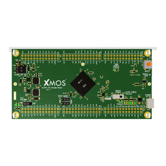
Boot XMOS Links Reset Clocking LEDs ARM Peripherals The Module Board contains the XMOS device plus support and debug circuitry. A single XS1-XA8A-10-FB265 device has its GPIO connected to the headers. Figure 2: xCORE-XA Module Board 2.1 Setup The Module Board is powered by a 5V external power supply. -
Page 6: Default Jumper Settings
XA Module Board Hardware Manual 6/19 2.1.1 Default Jumper Settings Power up : Jumpers J8 and J12 should be connected to “xCORE DEF ON” to have the xCORE power default to on. Boot mode: Jumpers J14 and J16 should be connected to “MSEL” for initial xCORE debugging. - Page 7 XA Module Board Hardware Manual 7/19 Figure 3: Debug LEDs Status Description Green The xTAG is powered on Green Target is running Target is in debug mode and stopped Green Target stop reason is expected e.g. breakpoint,print message Target stop reason is unexpected e.g.exception...
-
Page 8: Debug System Disable
XA Module Board Hardware Manual 8/19 2.3.2 Debug System Disable The debug system could be powered down(OFF) or enabled (ON) by setting the jumper J13. This allows the board in a standalone mode with typical power usage. 2.4 xCORE-XA Boot The boot mode jumpers J14 &... - Page 9 XA Module Board Hardware Manual 9/19 J1 Pin Designator Function Power supply 3.3V in/out Power supply 5.0V in/out Power supply ground RESET xCORE reset signal (active low) X0D00 P1A0 X0D01 P1B0 X0D10 P1C0 X0D11 P1D0 Power supply ground Not Connected...
-
Page 10: Arm Headers
XA Module Board Hardware Manual 10/19 J9 Pin Designator Function Power supply 3.3V in/out Power supply 5.0V in/out Power supply ground RESET xCORE reset signal (active low) X0D22 P1G0 X0D23 P1H0 X0D34 P1K0 X0D35 P1L0 Power supply ground Not Connected... - Page 11 XA Module Board Hardware Manual 11/19 J6 Pin Designator Function Power supply 3.3V in/out Power supply 5.0V in/out Power supply ground RESET ARM reset signal (active low) PCNT0 S0IN UART0 TX I2C1 SDA PCNT0 S1IN UART0 RX I2C1 SCL...
- Page 12 XA Module Board Hardware Manual 12/19 J4 Pin Designator Function Power supply 3.3V in/out Power supply 5.0V in/out Power supply ground RESET ARM reset signal (active low) ACMP1 CH0 ACMP1 CH1 PC10 ACMP1 CH2 PC11 ACMP1 CH3 Power supply ground...
- Page 13 XA Module Board Hardware Manual 13/19 J7 Pin Designator Function Power supply 3.3V in/out Power supply 5.0V in/out Power supply ground RESET ARM reset signal (active low) PD14 I2C0 SDA PD15 I2C0 SCL TIMER1 CC0 TIMER1 CC1 Power supply ground...
-
Page 14: Leds
XA Module Board Hardware Manual 14/19 J5 Pin Designator Function Power supply 3.3V in/out Power supply 5.0V in/out Power supply ground RESET ARM reset signal (active low) ACMP0 CH0 OPAMP0 OUTALT0 USART1 TX ACMP0 CH1 OPAMP0 OUTALT1 USART1 RX... - Page 15 XA Module Board Hardware Manual 15/19 Figure 4: ARM I/O Header with peripheral locations XM006580A...
-
Page 16: Add On Board Design
3 Add On Board Design The module board can be plug down into a application specific larger motherboard, or have smaller daughter boards plugged into it from above. Each set of I/O headers includes power, ground and reset for maximum flexibility. Flexible power supply options allow this board to be powered from a microUSB supply, supplying the add on board, or from the add on board, via the headers. -
Page 17: New Designs Based On Module Board
XMOS hardware reference designs must ensure are followed. The presence of a third party device in an XMOS hardware reference design does not make any statement about its general availability. You must make your own arrangements to ensure that all components can be sourced in the required volumes. -
Page 18: I/O
XA Module Board Hardware Manual 18/19 4.3 I/O Attention should be paid to the I/O planning for both the xCORE and ARM cores. The peripherals provided by the ARM core can be multiplexed to a variety of different pin groups, care should be taken to ensure there is no overlap. the xCORE I/O should be mapped, with care taken to ensure that port types are used appropriately, and that bi-directional usage for wide ports is avoided. -
Page 19: Errata
XMOS and the XMOS logo are registered trademarks of Xmos Ltd. in the United Kingdom and other countries, and may not be used without written permission. All other trademarks are property of their respective owners.
Need help?
Do you have a question about the xCORE XA and is the answer not in the manual?
Questions and answers