Advertisement
Quick Links
Installation Instructions
for LED Dimmer Switch
Works with 0-10V dimmable power
supplies or lighting fixtures only.
Model No.
LG-010VDM-U-PDL-WH
Rated
120-277V~
Voltage
Rated
60Hz
Frequency
Rated
600VA
Wattage
Load type
120V~
Rated Load
Electronic ballast
5A
or LED driver
Dimming
0-10V Dimming
method
Temperature: 32F - 104F
Working
Environment
Humidity:10% R.H. - 90% R.H.
Model Size
4.1in ×1.7in ×1.3in (L×W×H)
WARNINGS AND CAUTIONS
To avoid the risk of fire, shock, products should be installed in
accordance with electrical codes and regulations.
The product shall be used together with an upstream air-gap
switch.
Turn power off at circuit breaker or fuse,test if power is off before
installing.
After installed the dimmer, it is recommended to set the minimum
brightness level to make bulbs turn on immediately and the dimmer
with maximum dimming range. See ③ Figure 1.
If you are unsure about any part of these instructions, consult a
licensed electrician.
To avoid the risk of overheating and possible damage to the
equipment, do not install a receptacle, motor-operated appliance or
a transformer-operated appliance.
This product can only be used with 0-10V dimmable power supplies
or lighting fixtures, with 0-10V Dimming function.
When the dimmer is connected to multiple 0-10V dimmable power
supplies or lighting fixtures, do not mix different models when you
use it. Using the same model pls. Otherwise it will effect proper
function.
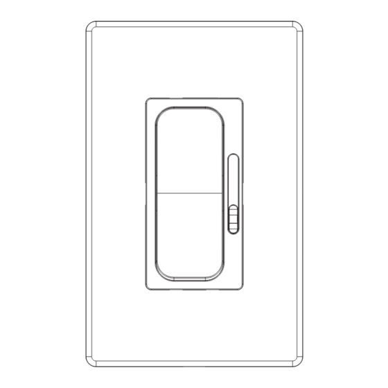
Functional parts instructions
① Slide Control Lever
Slide Control Lever ①
Move slide control lever up to increase brightness, move down to
decrease brightness.
Rocker Switch ②
277V~
Press the rocker switch of the dimmer, turn power on or off.
2A
Adjustment Button ③
Turn clockwise the adjustment button to increase brightness, turn
counter-clockwise to decrease brightness.
Adjustment button can adjust and set the minimum brightness
level of the lamps, make lamps turn on and dimmer with maximum
dimming range. Detail see step 7.
Figure 1
② Rocker Switch
③ Adjustment Button
Parts information
P3 Wire connectors(4pcs)
dimmer(1pc)
mounting screw(2pcs)
Tools needed to install your Dimmer
Φ5mm Philips
Electrical
3mm Slo ed
Screwdriver
Screwdriver
Tape
Pliers
Test Pencil
Ruler
Installation and testing
WARNING: To avoid fire and electrical shock,TURN OFF
Step 1
POWER at circuit breaker or fuse and test that power is
off before wiring.
Step 2
Removing existing switch: Remove existing wall plate and switch
mounting screws. Carefully pull switch from wall box, identify and
take out the wires attached to the switch, then remove the switch.
DO NOT remove wires which are taken out from the switch at this
time.(If new installation, disregard this step.)
Step 3
ldentifying your wiring application below.
If the wiring in the wall box does not resemble any of these
NOTE:
configurations, consult an electrician.
3-Way use
Single-Pole use
1
2
IMPORTANT: For 3-Way applications, note that one of the screw
terminals from the old switch being removed will usually be a
different color (Black) or labeled Common. Tag that wire with electrical
tape and identify as the common (Line or Load) in both the dimmer
wall J-box and 3-way wall J-box.
P2 Wire connectors(2pcs)
Cu ers
Advertisement

Summary of Contents for LUMEGEN LG-010VDM-U-PDL-WH
- Page 1 If the wiring in the wall box does not resemble any of these NOTE: configurations, consult an electrician. ① Slide Control Lever ② Rocker Switch ③ Adjustment Button Model No. LG-010VDM-U-PDL-WH Rated 120-277V~ Slide Control Lever ① Voltage Rated 60Hz...
- Page 2 Step 4a Connect the green dimmer wire to the green or bare copper ground wire Step 8 Single-Pole Wiring Application: Installing wall plate (See types below 8a,b) in the wall-box, and twist them with P3 wire connectors. Connect the black dimmer wire to the hot input wire with tag removed from Separated plate Step 8a the switch, and twist them with P3 wire connectors.
Need help?
Do you have a question about the LG-010VDM-U-PDL-WH and is the answer not in the manual?
Questions and answers