Advertisement
- 1 SAFETY MESSAGES
- 2 PRODUCT DESCRIPTION
- 3 VEHICLE IDENTIFICATION NUMBER (VIN)
- 4 VIN MATRIX - 13 DIGIT VIN
- 5 SPECIFICATIONS
- 6 SAFETY
- 7 OPERATIONS AND CONTROLS
-
8
ELECTRICAL SYSTEM
- 8.1 BATTERY INSPECTION & MAINTENANCE
- 8.2 BATTERY CLEANING
- 8.3 CONDITIONS WHICH AFFECT CHARGING
- 8.4 BATTERY CHARGING
- 8.5 RED LIGHT CHARGER ERROR CODES
- 8.6 REMOTE LED CHARGER CODES
- 8.7 CHECK / CHANGE CHARGING ALGORITHM
- 8.8 EXCESSIVELY DISCHARGED BATTERIES
- 8.9 BATTERY REMOVAL & INSTALLATION
- 8.10 TIPS FOR PROLONGING BATTERY LIFE
- 8.11 SINGLE POINT BATTERY WATERING SYSTEM
- 9 SERVICING YOUR PRODUCT
- 10 VEHICLE TROUBLESHOOTING
- 11 CONTROLLER TROUBLESHOOTING
- 12 STORAGE
- 13 PRODUCT WARRANTY
- 14 Documents / Resources
SAFETY MESSAGES
Safety messages and other information in this manual are preceded by the words DANGER, WARNING, CAUTION or NOTICE. They are printed in bold face, and are very important. We recommend you take special notice of this information.
 Danger indicates a hazardous situation which, if not avoided, will result in death or serious injury. |
 Warning indicates a hazardous situation which, if not avoided, could result in death or serious injury. |
 Caution indicates a hazardous situation which, if not avoided, could result in minor or moderate injury. |
NOTICE: Notices are messages not related to personal injury. They will provide key information to prevent property damage and to assure procedures are more easily understood or implemented.
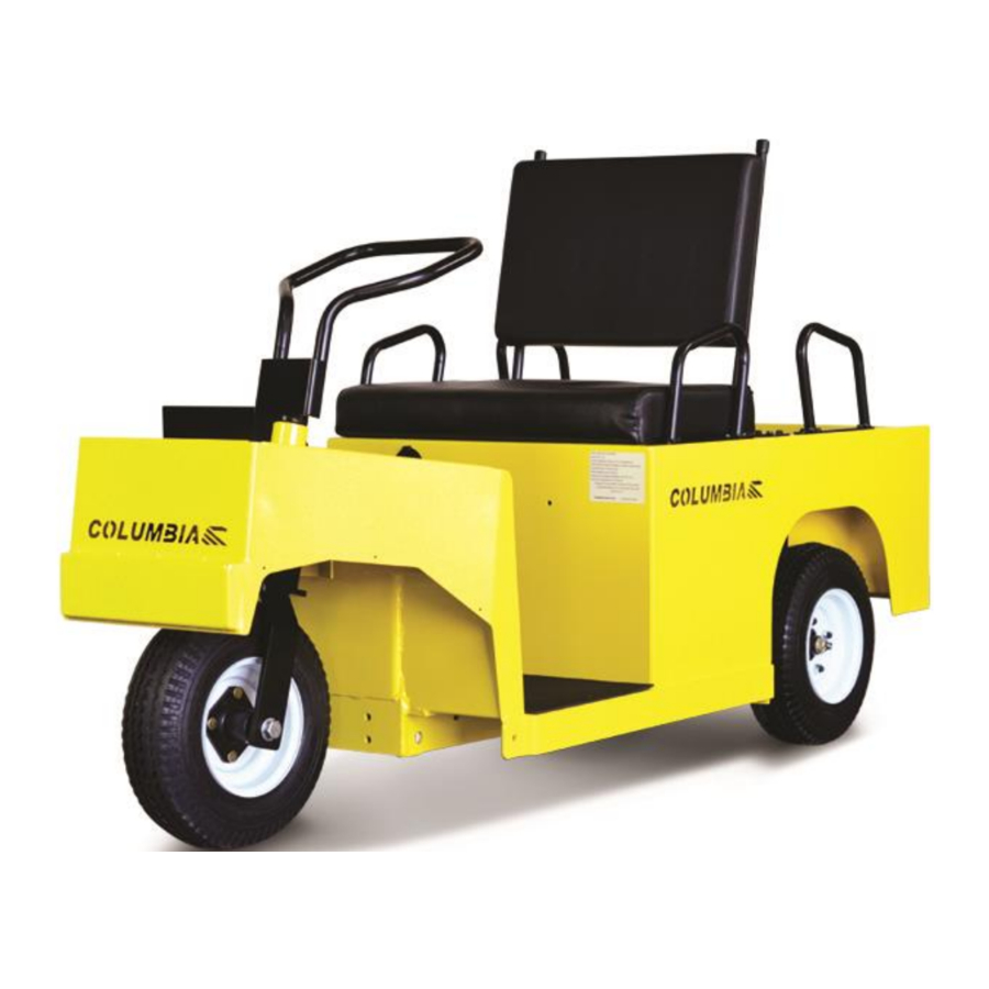
PRODUCT DESCRIPTION
The Expediter is a single operator vehicle involving sit-down operation, with capacity for one rear facing passenger. This vehicle is designed to be driven on smooth surfaces in and around industrial plants, warehousing, institutions, motels, mobile home parks, and resorts.
This vehicle is not designed to be driven on public highways. It is designed to conform to requirements for Type E vehicles as described in O.S.H.A. Standard Section 1910.178 (Powered Industrial Trucks) and with all applicable portions of the American National Standard for Personnel and Burden Carriers (ANSI B56.8 1993 Part III).
VEHICLE IDENTIFICATION NUMBER (VIN)
Each vehicle is assigned a unique Vehicle Identification Number (VIN). The VIN describes facts and features of the vehicle and contains thirteen (13) digits. The VIN can be found in two locations.
The VIN is recorded on the vehicle nameplate which is located on the left side of the operator's position.

The VIN is also stamped on the metal cross bar located under the rear deck platform.

The nameplate also has other important information such as vehicle weights and capacity. Do not exceed this capacity. This rated capacity includes cargo and operator.
To ensure prompt service when repairs or adjustments are required, your Columbia Dealer must have the VIN.
NOTICE: Always provide the complete VIN when contacting your dealer for technical assistance or maintenance and repair parts.
For your own personal reference, write down the VIN.
VIN MATRIX - 13 DIGIT VIN
| Digit 1 thru 3 = Abbreviation (Model) | ET2 = 3 Wheel, ET4 = 4 Wheel (EX21 - Expediter) |
| Digit 4 = Power System | E = Separately Excited Regenerative |
| Digit 5 = System Voltage | 2 = 24V, 4 = 48V |
| Digit 6 = VIN Spacer | - = normal |
| # = Special Product | |
| Digit 7 = Controller Amperage | 3 = 300A, 4 = 400A |
| Digit 8 = Axle/Brake System | Z = Rear Mechanical |
| Digit 9 = Build Year | Q = 2016, R = 2017, S = 2018 etc. (Letters I & O not used)* |
| Digit 10 Thru 13 – Build Sequence | 1234 |
SPECIFICATIONS
| EX21 T 24 | EX21 F 24 | EX21 T 48 | EX21 F 48 | |
| Passenger Capacity | One or Two | |||
| Max. Speed (mph) | 8 | |||
| Turning Curb to Curb (in) | 127 | 175 | 127 | 175 |
| Turning Intersecting Aisle (in) | 66 | 83 | 66 | 83 |
| Ground Clearance (in) | 4 | |||
| Wheelbase (in) | 52.5 | 53.5 | 52.5 | 53.5 |
| Overall Length (in) | 84 | |||
| Overall Width (in) | 28.5 | |||
| Overall Height (in) | 46.5 | |||
| Bed Size L x W (in) | 21.5 x 26.0 | |||
| Bed Height (in) | 20.5 | |||
| Tires | 4.8x8, LRB (Recommend 50 psi.) 4.8x8 Foam Filled 4.0x8 Solid Non-marking 4.8x8, Non-marking (Recommend 50 psi.) | |||
SAFETY
GETTING STARTED
For personal safety before operating the vehicle, it is the operator's responsibility to read, understand and follow the basic rules of operation and maintenance instructions in this manual. If you are responsible for the use of the vehicle, it is your responsibility to inform the person or persons using the vehicle about the following basic rules of operation for their personal safety.
It is Columbia ParCar Corp's specific recommendation that the following warnings must be observed at all times. Not all are repeated throughout this manual, but the recommendations included must be observed whenever these subjects (vehicle operation hazards, battery hazards, etc.) are encountered.
Please be a safe operator. Electric vehicles are only as safe as the person who is at the controls. If accidents are to be prevented, operators must accept their full measure of responsibility. While the designer, the manufacturer, the dealer and the safety engineer can help minimize the possibility of an accident, their combined efforts can be erased by a single careless act.
SAFETY GUIDELINES
Observe the following guidelines for safe operation.
- Define where vehicles may be driven.
- Define who should be allowed to drive the vehicle.
- Instruct first-time drivers.
- Maintain vehicles in a safe driving condition.
- Enforce safe-operating rules.
PRODUCT SAFETY STATEMENTS
This vehicle will not provide protection from lightning, flying objects, or other storm related hazards. If driving the vehicle in a storm, leave the vehicle and take shelter as per safety guidelines for your location.
Any modifications or changes to the vehicle that affect the stability, steering or result in increased speed beyond factory specifications could result in vehicle damage, severe personnel injury or death.
When replacement parts are required, use only genuine Columbia vehicle parts.
No modifications or additions, which affect the mechanical or electrical integrity and the safe operation of the unit, shall be made without the written approval of the manufacturer. If in doubt about any modification, contact your local Columbia Dealer or Columbia ParCar Customer Service.
Only trained service professionals should repair or service this vehicle. Persons doing even simple repairs or maintenance should have working knowledge and experience in general electrical and mechanical repair.
Follow all procedures exactly and observe all safety messages stated in this manual. Working on vehicles without following proper procedures and using proper equipment may result in vehicle damage or personal injury.
Moving parts hazard! When operating any vehicle in a stationary position, avoid components which could snag clothing or cause severe injury to body parts. A running vehicle must be worked on with the greatest care.
Failure to maintain vehicle properly could result in decreased vehicle performance, reliability or cause severe personal injury.
Always wear safety glasses or approved eye protection while performing vehicle maintenance.
This vehicle is not Federal or State DOT approved and is not equipped to be operated on public roads or highways.
Do not exceed the rated vehicle speed. Exceeding this speed may result in steering difficulty, motor damage, and/or loss of control and injury.
Never exceed the capacity ratings of the vehicle. Exceeding these limits may endanger occupant or cause vehicle damage.
Completely stop vehicle before stepping off.
If vehicle is to be left unattended, turn keyswitch to "OFF" and remove key.
Drive slowly in turns and up and down grades. Do not make turns on steep hills or inclines.
Do not operate while under the influence of alcohol or drugs.
To avoid the risk of injury or vehicle damage, operate at maximum speed only on smooth flat surfaces.
Allow additional stopping distance when traveling at higher speeds.
Do not drive this vehicle in hazardous areas unless this vehicle is approved and labeled for such operation.
ADDITIONAL OPERATION SAFETY CONCERNS
It is recommended that the operator and owner or renter of this vehicle comply with the OSHA requirements as stated in the Code of Federal Regulations, Section 29, 1910.178, Powered Industrial Truck Training Standard and the ANSI requirements as stated in Personnel and Burden Carriers ANSI B56.8.
As a minimum every operator should, in addition to the above requirements found in the standards noted above:
- Demonstrate a working knowledge of each control.
- Understand all safety rules and guidelines as presented in this manual.
- Know how to properly load and unload cargo.
- Know how to properly park the vehicle.
- Recognize an improperly maintained vehicle.
- Demonstrate ability to handle the vehicle in all conditions.
Every owner or renter of this vehicle must, at a minimum:
- Define where the vehicles should and should not be driven and utilized.
- Ensure all proper warnings as to driving hazards are properly displayed and visible.
- Install safety signage concerning hills, speed bumps, ramps, turns, blind crossings, intersections, etc.
- Define who should and who should not drive the vehicles.
- Enforce safe driving and operating rules.
- Provide driver training for first time operators and review safe operating recommendations regularly.
- Maintain vehicles in a safe operating condition and maintain a schedule for daily, weekly, monthly, quarterly, semi-annually and annual vehicle inspections.
- Determine who, when, and how should pre-operation inspections be conducted.
- Notify operators what should be done if an unsafe condition or operating problem is discovered.
OPERATIONS AND CONTROLS
IMPORTANT FIRST STEP
Upon initial delivery, it is very important that the battery pack is properly charged. This is required if the vehicle is to be stored for later use or is to be used immediately.
- Check that the batteries are not damaged or leaking and that connections are tight.
NOTICE: The following information does NOT apply to sealed batteries.
- Remove the battery vent caps and inspect each cell for proper electrolyte level. The battery manifold assemblies on vehicles with a single point watering system will require a ¼ counterclockwise turn to be removed for this inspection.
- If the electrolyte level is below the plates add only enough water to cover the plates.
NOTICE: Do not overfill a cell. Electrolyte expands and can overflow during charging.
- With the electrolyte level correct, use the on board charger to charge the batteries. Charging is complete when the remote LED is steady green.
- Vehicles without a single point watering system, after charging, refill cells to below the bottom of each cell vent.
INSPECTING THE UNIT
Upon receipt of vehicle, perform a pre-delivery inspection of the vehicle. Also, before using the vehicle, there are checks that must be performed to ensure that it is in safe proper working order.
NOTICE: Vehicle should be inspected immediately after delivery. Use the following guidelines to make sure there are no obvious problems.
Examine the contents of all packages and accessories that may have come in separate packages with this vehicle. Make sure everything listed on the packing slip is there. Items should not be broken or damaged.
Examine any visible wiring for obvious signs of damage. Check that all connections are secure. Check that battery connections are tight and all cells are filled to above plates. Check for damaged or leaking batteries.
Inspect the tires for obvious wear or damage. Check for proper tire inflation. Refer to manufactures recommendation imprinted on tire sidewall. Make sure that all wheel lugs are secure.
Check the body and other parts for obvious damage. Look for body damage, jagged edges etc. that may cause personal injury.
Operate each of the following controls before turning on the power keyswitch.
- Accelerator and Brake Pedals
- Steering Wheel, Handle Bar or Tiller Bar
NOTICE: Each control should operate smoothly and easily without sticking or requiring excessive effort.
Check that the horn sounds and that the key can only be removed when keyswitch is in the "OFF" position.
WHAT TO DO IF YOU HAVE A PROBLEM
If vehicle has just been delivered, report any physical damage or missing items to the shipping company and your local Columbia Dealer.
Report any service issue problems to the individual(s) responsible for correction and/or repair or contact your local Columbia Dealer for service.

If any problems are found, Do not operate vehicle until repairs are made. Failure to make necessary repairs could result in fire, severe personal injury, property damage or death. Consult your local Columbia Dealer for professional service.
CONTROLS

- KEYSWITCH
With the power keyswitch in the "OFF" position, the Traction System is powered down. This conserves battery energy by reducing the power draw when vehicle is not in use. Turning the power keyswitch to OFF is highly recommended whenever vehicle is not in use. Always take the key out of the keyswitch when leaving the vehicle. - DIRECTION SWITCH
When the direction selector is in the vertical position, the vehicle's direction signal is turned OFF or in neutral (N).
Turn direction selector to the right from vertical position to move the vehicle in forward (F) direction. Turn direction selector to the left from vertical position to move the vehicle in reverse (R) direction. A warning buzzer sounds when in reverse. - SYSTEM STATUS LIGHT
Vehicle will be equipped with an additional green System Status LED light located on the dash. With the power keyswitch in the "ON" position, the controller is powered up and this light should display a steady green light. If this green status light is not lit or is flashing refer to CONTROLLER TROUBLESHOOTING. - HORN SWITCH
Press button to sound horn. - LIGHT SWITCH
If equipped, the light switch is a two position switch. Move switch up to activate headlamp and tail lamp and down to run off. - BATTERY STATE OF CHARGE
This meter will display the battery state of charge. It is an analog gauge meter with an indicating needle and a colored background. It is a continuously reading meter. At rest with fully charged batteries the meter should read in the right white region.
When accelerating quickly, the needle will move to the left green region near the very far left red region. This is normal. If the needle continues past the green region into the very far left red region, it indicates that the batteries are 80% discharged (only 20% charge remaining). Recharge as soon as possible to avoid a shut-down of the vehicle.
When decreasing speed, the needle will move to the right as electrical energy is being "regenerated" back into the batteries. - HOUR METER
If equipped, the hour meter indicates the total number of hours the vehicle has been operating. - OPERATING INSTRUCTION LABEL
Quick guide for basic operating instructions.

- ACCELERATOR PEDAL
The accelerator pedal controls the speed of the vehicle in the same manner as a conventional automobile. The pedal must be fully released when changing directions.
To avoid injury, speed in reverse should always be kept at a minimum.
Be sure the direction selector is in the desired direction of travel before depressing the accelerator pedal.
- BRAKE PEDAL / PARKING BRAKE
Depress the brake pedal to slow or stop the vehicle. Pressing the brake pedal activates the brake light.
The parking brake is controlled by the brake pedal. To lock for parking, depress the pedal and rock forward to engage the parking brake. To release, press on the rear of the brake pedal. Always apply parking brake when leaving the vehicle.
NOTICE: Do not operate the vehicle with the parking brake applied. Damage to the vehicle could result.
NOTICE: Never rest your foot on brake pedal while operating the vehicle. This wears brake pads, creates drag and causes excess battery discharge.
- WARNING LABEL
Read this information carefully before operating the vehicle. Promptly replace if removed or damaged. Contact Columbia ParCar for replacements if needed. - ADDITIONAL INFORMATION LABEL
Transportation and/or storage advisory.
NOT SHOWN: Vehicle is equipped with a seat switch interlock system which requires operator in seat for traction drive to operate. If operator is not present when accelerator is pressed, system status light will flash two times.
PRE-OPERATION CHECKLIST
Before operating the vehicle always inspect the items listed in the following checklist. Should any item malfunction or need adjustment. Do not operate vehicle until the problem has been corrected.
| ITEM | PROCEDURE | |
| Batteries | Fully charged or adequately charged to provide power for duration of operations. | |
| The AC cord is disconnected from the vehicle. | ||
| Electrolyte level in each cell covers the top of cell plates. | ||
| Batteries are secure and free of corrosion. | ||
| All terminals and connections are tight. | ||
| Tire Pressure | Inflated to the specifications labeled on the tire sidewall. | |
| Horn | Press horn button to sound horn. | |
| Beeper | Reverse beeper sounds when R is selected for direction of travel. Note: Some units may be programmed to sound in F and R. | |
| Accelerator | Operates smoothly and fully releases to a raised position. | |
| Brake Pedal | With pedal in the upright position, the vehicle should be able to be moved freely. With pedal in the down and locked position, the vehicle should not move. | |
| Labels | All warning and operation labels in place. | |
| Steering | Responsiveness and the absence of excessive free play. | |
| Cargo | Secured to the bed platform. | |
| Load is balanced and not top heavy. | ||
| Obstacles | Path of intended travel is free for obstructions. | |
OPERATING INSTRUCTIONS
DRIVING THE VEHICLE
- Do not operate vehicle unless you are a qualified and trained operator.
- Keep the vehicle under control at all times.
- Drive only on level surfaces or on surfaces having an incline of no more than 10%.
- Drive slowly when making a turn, especially if the ground is wet, slippery or when driving on an incline.
- Do not drive this vehicle in hazardous areas unless this vehicle is approved and labeled for such operation.
- Do not drive over loose objects, holes or bumps.
- Observe all traffic regulations and speed limits.
- Keep to the right of traffic under normal conditions.
- Maintain a safe distance from all objects and other vehicles.
- Yield right of way to pedestrians, ambulances, fire trucks or other vehicles in emergencies.
- Do not overtake another vehicle at intersections, blind spots or other dangerous locations.
- Keep a clear view ahead at all times. Slow and sound the horn when approaching a corner or other blind intersection.
- Immediately report any accident or vehicle problem to your supervisor.
- Do not load cargo that can easily fall off this vehicle.
- Do not exceed the cargo load capacity of this vehicle.
ADJUSTING BACKREST POSITION
For carrying one rear facing passenger, lift backrest and fold it rearward. In the down position, it becomes the seat for the rear facing passenger. Passenger to observe the warning label and use the hand holds while vehicle is moving.

When operating without passenger, lift backrest completely and drop into upright position.
- Never carry passenger unless backrest/seat is in "down" position.
- Always verify that passenger is seated and gripping hand hold bars before proceeding.
- Never transport more than one operator and one passenger.
STEERING
Three types of steering are used on these vehicles. Each control the path of the vehicle exactly the same as a conventional automobile steering wheel or bicycle handlebars.
Be sure to have both hands on the steering wheel at all times. Do not turn the vehicle sharply at high speeds.
ELECTRICAL SYSTEM
The type of battery used in a Columbia vehicle has a service requirement which is quite different from that of an automotive battery.
The electric vehicle battery supplies all of the power to drive the vehicle. During operation the power stored in the batteries is expended. While the amperage drain rate can vary greatly depending on the type of service, the duration of use and the number of "starts" and "stops" made during a day, the batteries nevertheless progress through each duty cycle from "fully charged" to an almost depleted state. This type of service is known as "deep cycle" service and electric vehicle batteries are specifically designed to handle this type of service.
Proper performance of your Columbia Vehicle can only be obtained from specified deep cycle, electric vehicle batteries.
PLEASE REVIEW IMPORTANT DANGER STATEMENTS WHEN WORKING NEAR BATTERIES AND CHARGING SYSTEMS!
Battery acid is poisonous and can cause severe burns. Avoid contact with skin, eyes, or clothing.
ANTIDOTES:
EXTERNAL: Flush with water. Call a physician immediately.
INTERNAL: Drink large quantities of milk or water. Follow with milk of magnesia or vegetable oil. Call a physician immediately.
EYES: Flush with water for fifteen minutes. Call physician immediately.
Always remove key and disconnect battery pack before servicing or repairing the vehicle. See BATTERY DISCONNECT METHOD.
Always wear full-face shield when working on or near batteries.
All batteries used in electric vehicles can explode! Batteries produce explosive hydrogen gas at all times, especially, during charging or discharging. Ventilate area when charging batteries.
Do not attempt to charge a battery if it is frozen, or if the case is bulged excessively. Frozen batteries can explode! Properly dispose of the battery.
Do not smoke around batteries. Keep sparks and flames away from batteries and the charging area. Use care to prevent an accidental arc which could cause an explosion. Use only approved insulated tools, remove jewelry such as rings, watches, chains etc. and place an insulating material (wood, plastic, rubber etc.) over all battery connections.
Never add acid to a battery.

To reduce the risk of electrical shock or injury:
Do not use an ungrounded two to three-prong adapter to connect the charger to a twoprong outlet or extension cord.
The battery charger must be properly grounded. Use a three prong No. 12 AWG heavy duty power cord no more than 50 feet long.
Locate all cords so that they will not be stepped on, tripped on, or otherwise damaged. Immediately replace worn, cut, or damaged power cords or wires.
Do not connect the power cord near fuels, grain dust, solvents, thinners, or other flammables. The spark can ignite flammable materials and vapors
NOTICE: Automotive batteries should never be used for "deep cycle" application, as their useful life will be very short.
Damaged or corroded battery terminals should be replaced or cleaned as necessary. Failure to do so may cause overheating during operation. Torque connections to 100 in. lbs.
Do not attempt to recharge batteries with a charger not designed for your vehicle.
Only trained technicians should service the charger. Contact your Columbia Dealer for assistance.
NOTICE: Install surge arrestors on incoming AC power lines. Surge arrestors will help protect electrical/electronic components in the charger and vehicle from all but direct or "close proximity" lightning strikes.
BATTERY INSPECTION & MAINTENANCE
- Be sure battery hold downs are properly tightened. A loose hold down may allow the battery to become damaged from vibration or jarring. A hold down that is too tight may buckle or crack the battery case.
- Weekly inspect battery posts, clamps and cables for breakage, loose connections and corrosion. Replace any that are damaged. Batteries and connections must be clean and dry. Torque connections to 100 in. lbs.
- Weekly an equalization charge is to be applied to the battery pack. This process balances the electrical charge in the battery pack and will extend battery life. The following procedure is used to complete this.
- Charge the battery pack allowing the charger to go to green 100% charge.
- Once the green LED lights unplug the power cord.
- Wait approximately 30 seconds. Reconnect the power cord and allow the charger to complete a second charge cycle.
- If the vehicle is not to be used, leave power cord connected. The on-board charger can test and recharge as needed.
NOTICE: Automotive batteries should never be used for "deep cycle" application, as their useful life will be very short.
Install surge arrestors on incoming AC power lines. Surge arrestors will help protect electrical/electronic components in the charger and vehicle from all but direct or "close proximity" lightning strikes.
Damaged or corroded battery terminals should be replaced or cleaned as necessary. Failure to do so may cause overheating during operation.
Do not attempt to recharge batteries with a charger not designed for your vehicle.
Only trained technicians should service the on-board charger. Contact your Columbia Dealer for assistance.
BATTERY CLEANING
Acid-soaked debris on the battery terminal connections will cause current leakage, reduces battery efficiency, and battery life.
Hose wash battery terminal connections periodically with clean low-pressure water to keep them free of acid spillage, dirt, and other debris. Do not hose wash electronic controllers, switches, solenoids and other electrical control devices. Cover as necessary to prevent splashing. Clean battery terminal connections with baking soda (sodium bicarbonate) and water solution. Mix 5 teaspoons baking soda per quart of water. Use a stiff bristle brush, rinse with clean water and dry with a clean cloth. Torque connections to 100 in. lbs.
NOTICE: The following information does NOT apply to sealed batteries.

- Check the electrolyte level on new batteries before they are put into service, and, at a minimum, once a week thereafter. Water use increases as batteries age. If the vehicle is equipped with a Single Point Battery Watering System see the information on this in this section.
- Never allow the electrolyte level (A) to fall below the top of the plates (C). If the plates are exposed, add only enough to cover the plates before charging.
- After batteries are fully charged, fill cells to just below the bottom of the cell vents (B), approximately 1/8" to 1/4". Electrolyte level should not touch the bottom of the cell vents.
- Do not overfill batteries. Electrolyte expands and can overflow during charging. Water added to replace the spillage dilutes the electrolyte and reduces its specific gravity.
- Use only distilled water. Vehicle batteries may use up to 16 quarts of water during their useful life and non-distilled water may contain harmful minerals which will have a cumulative adverse effect on battery performance and life.
- Check to see that battery cap vent holes are clear. Plugged vent holes will not permit gas to escape from the cell and could result in battery damage. Check that all vent caps are tightly in place. Do not allow water or cleaning solution to enter cap vent holes.
NOTICE: Follow local ordinances and codes for proper disposal of battery cleaning waste.
CONDITIONS WHICH AFFECT CHARGING
Always schedule enough charging time so the charger attains the 100% level. Charging time is affected by age and battery condition, state of discharge, electrolyte temperature, AC line voltage, and other variables. Correct charging methods extend battery life and vehicle range between charges. If vehicle is used only occasionally, a refresher charge should be given prior to using.
New batteries need up to four hours more charging than "mature" batteries. Before the first use, completely charge new batteries. Charging time will vary based on conditions noted above but will probably be 12 hours.
Limit new batteries use between charges for the first 25 – 50 cycles. New batteries have less capacity than seasoned batteries. New batteries should not be discharged more the 20 – 30% before recharging. This will prevent premature battery failure.
Battery efficiency is affected by temperature. If the temperature of the outside air and/or batteries is below 60º F, battery capacity is reduced. Batteries will require more frequent and longer charge periods in early spring, fall and winter.
As batteries age, they finish charge at progressively higher charge rates and tend to use more distilled water. At this point in battery age, charger will automatically begin reducing charge time.
Batteries found defective must be replaced. All batteries in a vehicle should be matched according to age, capacity and brand.
BATTERY CHARGING
Connect the supplied power cord to the vehicle charger receptacle and to a properly grounded 120 volt AC supply minimum 20 amp circuit wall outlet. Charger start and charge time is automatic. The receptacle is located directly beneath the key switch on the right side of the console.
Charger start and charge time is automatic. The remote LED will be flashing short green. If this LED is not lit check the AC connection and the AC source fuse or breaker. If this fails to correct the problem, contact your Columbia Dealer for assistance.
Charger will automatically turn on and conduct a short self-test and battery pack test. The LED will flash in sequence and then a trickle current will be applied to batteries until a minimum voltage is reached.
If the batteries meet the minimum voltage requirements of the charger, signifying they are serviceable (chargeable), the charger enters the bulk charging (higher amperage-constant current) stage. The remote LED will be flashing short green.

NOTICE: If the batteries are excessively discharged, the charger will not be able to charge the complete set of batteries. The remote LED will be flashing red (see Red Light Charger Error Codes). It will then be necessary to follow the Special Charging for Excessively Discharged Batteries.
When the charger has completed approximately 80% state of charge the remote LED will flash long green as the last 20% of charge is returned to the batteries in the second phase (constant voltage phase).
NOTICE: You can terminate charging at this point if necessary. The vehicle can be used, but completing the charge cycle is highly recommended.
A Green LED continuously lit indicates the batteries are completely charged. The charger may now be unplugged from the AC source. If the batteries will not be used for a length of time, check monthly for the charge level. It is also acceptable to leave the charger plugged in. The charger has the capability to test and recharge if necessary.
Repeated "Short Charging", leaving the charge short of 100% will shorten operating cycle distance and reduce battery life.
A fault occurring while charging causes the remote LED to flash with a code relaying the error. Some errors may require repair by a qualified technician and others may be simply transient and will automatically recover when the fault condition is eliminated and the charger cycled by disconnecting the AC source for a minimum of 11 seconds.
NOTICE: A Yellow (Amber) flashing remote LED indicates the thermostatic control has limited the charger output due to ambient temperature conditions. It is still charging, but at a reduced rate.
RED LIGHT CHARGER ERROR CODES
1 FLASH = Battery Voltage High: Auto-recover. May be temporary condition, or wrong charger installed, i.e. 36 volt charger on 48 volt battery pack.
2 FLASH = Battery Voltage Low: Auto-recover. Confirm each individual batteries minimum voltage with a voltmeter. Two or more 6 volt batteries register less than 5.85 volts, or accumulative total pack voltage has been discharged to less than 20% remaining. Vehicle operation will cease until batteries are recharged.
3 FLASH = Charge Timeout: The charging did not complete in allowed time, 12-14 hours. This may indicate a battery problem, or that the charger output was reduced due to high ambient temperatures. Disconnect AC supply, confirm sufficient ventilation, allow cool down time, and restart charger.
NOTICE: If the charger is exhibiting a 3 flash fault and it has been determined that the cause was not due to ventilation or high ambient temperature, the following procedure may restore the battery pack to normal operation.
- Battery posts and terminals must be clean and free of corrosion.
- For non-sealed batteries, check that electrolyte level just covers plates.
- Plug in charger for at least a 16 hour charge.
- Drive the vehicle for less than half the distance normally driven.
- Repeat the above steps until the charger goes green 100% charge on a 16 hour charge.
4 FLASH = Check Battery: The batteries could not be trickle charged up to a minimum level to start charger. This may be the result of badly discharged batteries, or one (or more) damaged cells. See EXCESSIVELY DISCHARGED BATTERIES.
5 FLASH = Over-Temperature: The charger shutdown due to high internal temperature. May require reset (AC unplugged) and cool down to restart charging cycle. This fault may indicate inadequate cooling airflow or high ambient air temperatures. Check for debris or blockage at cooling fins. Move the vehicle to a cooler, well ventilated area, or adjust time of day when charging.
6 FLASH = Charger Fault: A fault was detected either in the batteries or in the charger. The batteries must be tested to ensure there is no damage to one or more cells. If the batteries are found to be good, the charger may need to be replaced by a qualified technician.
A STEADY RED FAULT LED confirms an internal electrical fault of the charger and requires charger replacement and return.
REMOTE LED CHARGER CODES
STEADY GREEN = Battery pack is = 100% charged.
SHORT GREEN FLASH = Battery pack is =< 80% charged.
LONG GREEN FLASH = Battery pack is => 80% charged.
SHORT AMBER FLASH = Battery pack is =< 80% charged, high internal charger temperature.
LONG AMBER FLASH = Battery pack is => 80% charged, high internal charger temperature.
RED FLASH = Charger detected a fault, see codes listed above.
CHECK / CHANGE CHARGING ALGORITHM
The charger has been programmed for use with the Columbia ParCar supplied batteries and contains algorithms for use with different batteries. Table A details these battery models.
| TABLE A | |
| ALGORITHM | BATTERY TYPE |
| 126 | Full River 100Ah AGM |
| 125 | Full River 200Ah AGM |
| 72 | Generic 250-335 Ah Flooded Constant power dv/dt |
| 43 | Discovery AGM |
| 42 | Discover AGM 80 – 150 Ah |
| 11 | Generic 200-255 Ah Flooded Constant power dv/dt |
| 5 | Trojan 30XHS |
| 4 | US 2200, US 145 (Standard) |
| 1 | Trojan Flooded |
NOTICE: For maximum battery life the correct algorithm must be used.
If your battery model is not listed in Table A, contact Columbia ParCar for further information
Each time AC power is applied with the battery pack NOT connected, the charger enters an algorithm select/display mode for approximately 11 seconds. This will be displayed on the remote LED.
During this time, the current algorithm # is indicated on the LED light. A single digit algorithm # is indicated by the number of blinks separated by a pause. A two digit algorithm # is indicated by the number of blinks for the first digit followed by a short pause, then the number of blinks for the second digit followed by a longer pause.
To check/change the charging algorithm:
Disconnect the charger positive connector from battery pack. Apply AC power and after the LED test, the algorithm # will be displayed for 11 seconds.
To change the algorithm, touch the positive connector during the 11 second display period to the battery pack's positive terminal for 3 seconds and then remove. The algorithm # will advance after 3 seconds. Repeat until the desired algorithm # is displayed. A 30 second timeout is extended for every increment. Incrementing beyond the last algorithm moves back to the first algorithm. After the desired algorithm # is displayed touch the charger connector to the battery positive until the output relay is heard to click (~ 10 seconds). The algorithm is now in permanent memory.
Remove AC power from the charger and reconnect the charger positive connector to the battery pack. It is highly recommended to check a newly changed algorithm by repeating the above steps.
EXCESSIVELY DISCHARGED BATTERIES
NOTICE: Your Columbia Dealer will have the equipment and experience to perform the following battery inspections
The charger will not charge dead batteries. First establish that none of the batteries have an internal fault or bad cell. If a battery has remained too long in a discharged state (i.e. 2-4 volts each), it may be internally damaged and not capable of accepting a charge and must be replaced.
If the electrolyte Specific Gravity is low (less than 1.1098 SG) or individual battery voltage is less than 5.25 volts for three cells (10.5 volts for six cells), recharge each battery with an ordinary automotive style trickle charger at a rate of 3 to 6 amps.
It is not necessary to disconnect the battery cables, as the alligator style clips can be connected to each positive and negative battery post. Follow specific charger instructions.
To prevent a spark from igniting the gas emitted from the batteries, always disconnect the charger AC power cord first when moving the positive/negative alligator clips.
Be sure to charge all of the batteries in the set. Each battery may require two to three hours of charging to bring it back to serviceable condition. After all batteries have been individually charged, remove the automotive charger and restart charging with the on-board charger. It may require several 8-12 hour cycles to bring severely discharged batteries back to 100% charged condition. If again the charger has the RED FAULT LED flashing there is a problem with one or more of the batteries.
BATTERY REMOVAL & INSTALLATION
- Remove battery negative (-) cables and then battery positive (+) cables.
- Remove battery hold down.
- Remove batteries from vehicle.
- To install batteries, reverse the removal procedure with the negative (-) cables being attached last. Torque connections to 100 in. lbs.
TIPS FOR PROLONGING BATTERY LIFE
NOTICE: A common misconception is Deep Cycle Batteries develop a memory, lose capacity, or must be discharged until the BDI warning flashes and then recharged. Deep Cycle Wet Lead Acid Batteries are not like cell phone NiCad Batteries. Deep Cycle Batteries benefit from frequent charging and being maintained at as close as possible to a 100% state of charge. Plugging in the on-board charger overnight or when the vehicle is not in use for 3-5 or more days is encouraged.
- Recharge batteries as soon as they become 20% or more discharged (less than 1.238 sp. gr.).
- Make it a regular habit to plug in the charger when the vehicle is not in use. Batteries may be recharged if vehicle has been driven 15 minutes or more since the previous charge.
- Make sure your electrical outlet is operational.
- Never go below 20% state of charge (or 80% discharged) without recharging immediately. Allow 14 – 16 hours of charging.
- Batteries will provide a longer life if not deeply discharged. Batteries that are regularly deeply discharged will require more work by the charger and will have a shorter life.
- For non-sealed batteries, make it a regular habit to check (and water) your batteries after charging. Always add water after charging. This will reduce the chance for overflow due to expanding water.
- Weekly equalize the battery pack.
- If the vehicle is not operated daily the Power keyswitch should be turned off. This will power down the traction control system and reduces power loss on the batteries.
- Batteries in storage may self discharge and should be recharged when the specific gravity falls below 1.238 sp. gr. or individual battery voltage is less than 5.25 volts for three cells (10.5 volts for six cells).
SINGLE POINT BATTERY WATERING SYSTEM
(If equipped)
NOTICE: The following information does NOT apply to sealed batteries
This is a single point watering system for maintaining a sufficient electrolyte level in the batteries.
The fill tube assembly which is used for adding water to the battery pack consists of a fill tube, one end having a filter screen, the other having a female coupler and a rubber squeeze bulb.
Check the battery pack water level weekly by:
- Inserting the fill tube filter end in an approved water supply.
- Attaching the female coupler to the battery pack male coupler. Squeeze the rubber ball until firm which indicates that filling is complete. Immediately disconnect the couplers by depressing the push button on the female coupler. If the water supply is left connected after the filling process is finished it could lead to an overfill.
SERVICING YOUR PRODUCT
MAINTENANCE SCHEDULE
OWNER/OPERATOR
| Item | Operation | Weekly | Monthly | Semi-Annual |
| Tires | Lug nuts tight. | * | ||
| Check tire pressure, wear, damage. dented rims. | * | |||
| Electrical | Check battery electrolyte level. | * | ||
| Apply equalization charge to the battery pack. | * | |||
| As required, clean battery terminals and wash cases. | * | |||
| Check the general condition of the electrical system (connections, frayed/broken cables). | * | |||
| Brakes | Check pedal & park brake operation. | * | ||
| Body and Frame | Inspect for loose hardware (bolts & nuts). | * | ||
| Clean body and seats, Wash as needed. | * | |||
| Lube | Visually check suspension and differential for leakage. | * |
QUALIFIED TECHNICIAN
It is recommended that the following be performed by a trained qualified technician or your Columbia Dealer.
| Item | Operation | Quarterly | Semi-Annual | Annual |
| Tires | Front wheel alignment. | * | ||
| Electrical | Test batteries. | * | ||
| Inspect motor condition and operation. | * | |||
| Brakes | Check brakes, clean, adjust, replace if needed. | * | ||
| Check brake fluid (when equipped) | * | |||
| Lube | Check differential fluid level. | * | ||
| Grease fittings. | * | |||
| Wheel | Check wheel axle nuts for tightness & torque. | * | ||
| When equipped,- wheel bearings, repack, replace if needed | * |
MAINTENANCE GUIDELINES
To ensure that the vehicle is kept in a safe and correct operating condition, it must be inspected and maintained on a regular basis. Proper lubrication, electrical control adjustments, safety feature checks, etc. performed at recommended intervals will help prevent damage or failure of the unit while providing optimum performance.
To perform many of the maintenance items detailed below, it will be necessary to remove the vehicle deckboard. Care should be exercised while removing the deckboard.
Follow the guidelines below to assure proper maintenance.
- Allow only trained maintenance personnel to maintain, repair, and inspect the vehicle.
- Before starting any repairs or maintenance, immobilize the vehicle by turning the power keyswitch off, removing the key and setting the park brake.
- Disconnect both of the main battery pack leads before working on or disconnecting any electrical component or wire.
- Block the chassis with jack stands before working under a raised vehicle.
- Conduct vehicle performance checks in an authorized area where a safe clearance exists.
- Before starting the vehicle, follow the recommended safety procedures.
![]()
Avoid fire hazards and have fire protection equipment present in the work area.- Do not use flammable fluids for cleaning parts.
- Work in a properly ventilated work area.
- Regularly inspect and maintain in safe working condition the brakes, steering mechanisms, speed and directional control mechanisms, warning devices, guards and safety devices.
![]()
Keep the vehicle in a clean condition to minimize fire hazards and facilitate detection of loose or defective parts.

LIFTING INSTRUCTIONS
- Make sure that front tires are facing straight ahead.
- Tie steering wheel to prevent turning.
- Place jack under one side of vehicle on frame rail at point midway from front and back of vehicle.
A vehicle is extremely unsteady when one side is raised. Use care to prevent tipping or roll over
- Raise one side of vehicle with jack, and place a 6-8" block under both front and rear of vehicle being raised.
- Slowly lower jack and move it to opposite side of vehicle.
- Repeat lifting procedure previously described and position blocks corresponding to those on opposite side as described above.
- Slowly lower jack and ensure that vehicle is supported by four blocks.
- To lower vehicle, use above procedure in reverse order.
BRAKE PEDAL
The mechanical brakes consist of two rear drum brakes which are self-adjusting. Monthly, with the vehicle stationary, depress the brake pedal and check for not less than 1/2" pedal free travel before resistance is felt. Maximum pedal free travel should not exceed 2".

The parking brake is applied by depressing the parking brake pad at the top of the brake pedal which locks the brakes in place. If the brakes fail to hold the vehicle in position, contact your Columbia Dealer for qualified service assistance.
Should the free travel or the stopping action of the brakes be in question, do not use the vehicle. Contact your Columbia Dealer for qualified service assistance.
TIRE CARE
Improper inflation will shorten the life of your tires and will adversely affect performance. For proper tire inflation refer to vehicle specifications.
NOTICE: Replacement tires must be the same size as original equipment. Increased tire load ratings are permissible but tire rating does not increase the rated load carrying capacity of the vehicle.
WHEEL & TIRE REMOVAL/INSTALLATION
Place blocks ahead of and behind the wheels that will remain on ground. Slightly loosen lug nuts. Place jack under one side of vehicle on frame rail at point midway from front and back of vehicle. Raise vehicle and remove lug nuts and wheels. To install, tighten the lug nuts evenly in a star pattern until the nuts are all seated and torque to. 65 ft. lbs. Recheck lug nut torque with the vehicle on the ground.
NOTICE: The wheel may be bent if not torqued in a crossing pattern. This will cause the wheel to wobble.
CLEANING
Wash underside to remove all dirt and debris. Do not direct high pressure water at the controller, speed switches, or tops of the batteries.
Wash body with a mild detergent. Do not use abrasives (bodies are painted).
LUBRICATION
For three wheel vehicles, semi-annually grease the single front hub assembly. For four wheel vehicles, semi-annually grease the two steering arm spindles. Use a high quality wheel bearing grease. Remove the weight from the front suspension before lubricating to ensure proper grease distribution.

The differential should be checked periodically for signs of leakage. Contact your Columbia Dealer for fluid replacement.
VEHICLE TROUBLESHOOTING
| PROBLEM | CHECK |
Will not move | Keyswitch on. Keyswitch is in desired direction. Keyswitch for loose wires or faulty switch. |
| Batteries for loose terminals, corrosion, electrolyte level or state of charge. | |
| Motor for loose wires, open circuits. | |
Runs slow | Batteries for loose terminals, corrosion, electrolyte level or state of charge. |
| Brakes dragging | |
| Under inflated or flat tires. | |
| Wheels for binding, do not spin freely. | |
| If these test procedures do not resolve your vehicle problem, contact your Columbia Dealer for service. | |
CONTROLLER TROUBLESHOOTING
The controller is located under the rear deck next to the axle. The controller has a green LED diagnostic light which is a good tool to indicate a fault in the electrical system. The vehicle is also equipped with a dash System Status LED, it functions the same as the controller LED.

It is essential to observe the flashing pattern (number of blinks followed by a pause) of the LED light any time the vehicle is not operating as expected. The number of blinks is very useful for your servicing dealer to accurately and quickly diagnose any faults that exist.
However, two of the flash codes may indicate an operation fault, and likely do not require component changes or dealer service.
A "2 Flash fault" may indicate a start-up sequence fault. This is caused when the vehicle direction selector is not in the neutral position when the power keyswitch is turned on. Steps to take to possibly clear this fault are:
- Set the parking brake.
- Turn vehicle power keyswitch to OFF.
- Set direction selector to N – Neutral.
- Ensure the accelerator pedal is at its resting (up) position.
- Turn vehicle power keyswitch to ON.
- Select the desired direction on the direction selector.
- Release parking brake and depress accelerator.
A "7 flash fault" may indicate that the battery voltage is too high or too low for the vehicle power system. Voltage too high occurs when rapidly descending hills with a vehicle equipped with the ACEplus Regenerative braking system. The electrical system creates current which causes a spike in battery voltage.
To prevent this, always travel at a safe, prudent speed when driving on declines, especially with freshly charged batteries. To possibly clear this fault turn the power keyswitch to OFF and back to ON. If there is still a "7 flash fault", the battery voltage may be low. Check and charge batteries or replace batteries.
STORAGE
BATTERY PREPARATION FOR STORAGE
Before storage make sure batteries are fully charged, for non-sealed batteries make sure the electrolyte is full in all cells. Clean the batteries and connections as described earlier.
The charger has the capability to test and recharge batteries during storage. Leave the batteries connected and the charger plugged into a reliable AC source.
If the on-board charger is not used the batteries will "self-discharge" during storage and recharging will be necessary. Below is the recommended frequency for recharging.
| STORAGE TEMPERATURE | CHARGE AT |
| Below 4°C (40°F) | Every 6 months |
| 4°C - 16°C (40° – 60°F) | Every 2 months |
| Above 16°C (60°F) | Once a month |
The voltage or specific gravity of the electrolyte should be checked every 6 to 8 weeks using a voltmeter or hydrometer.
After charging, disconnect the batteries.
NOTICE: Batteries in a low state of charge will freeze at higher temperatures than fully charged batteries. Do not attempt to charge a battery that is frozen or if battery case is excessively bulged. Properly dispose of battery, because frozen batteries can explode.
The table below indicates freezing points of batteries at different specific gravities.
| SPECIFIC GRAVITY | FREEZE POINT °F/°C |
| 1.260 | -70/-57 |
| 1.230 | -39/-38 |
| 1.200 | -16/-26 |
| 1.117 | -2/-19 |
| 1.110 | +17/-8 |
Notice: Specific gravity readings are at 80°F. Values need adjustment for electrolyte temperature. Reduce.004 for every 10°F below 80°F. Increase by that amount for every 10°F above
Quarterly during storage check water levels for non-sealed batteries.
PRODUCT PREPARATION FOR STORAGE
Store the vehicle in a cool place.
Maintain tire pressure at recommended PSI.
Grease suspension and continue quarterly lubrication during storage period.
Clean vehicle body, seats, battery compartment and vehicle underside.
Do not engage park brake. Block wheels to prevent movement.
NOTICE: Make sure power keyswitch is in the OFF position.
RETURNING THE PRODUCT TO SERVICE
- If necessary, connect the battery pack and fully recharge batteries.
- Check tire pressure and readjust if necessary.
- Perform Pre-Operational Checklist.
For vehicles with a single point watering system:
- After the batteries have been fully charged, connect the system to its water supply for 3-5 seconds then disconnect regardless of whether or not the batteries are completely full.
- Return the vehicle to its regular service.
- Place the vehicle back into its regular watering schedule (waiting at least 1 week until next watering).
TOWING
NOTICE: Columbia ParCar does not recommend towing this vehicle.
TRANSPORTING
NOTICE: Never transport a vehicle behind an auto or truck unless on an approved trailer.
When trailering your vehicle over long distances or on the highway observe the following:
- Use trailers specifically designed to carry your Columbia ParCar vehicle that meets all federal, state and local requirements.
- Secure vehicle to the trailer following trailer manufacturer's instruction.
- The key should be removed from the vehicle, the parking brake firmly locked, and the wheels blocked.
- On vehicles equipped with high or wide additions or accessories be certain they are secured properly to prevent loss or damage while trailering.
PRODUCT WARRANTY
To obtain warranty service, you must return your vehicle during the warranty period to any authorized Columbia vehicle repair facility. Further information regarding warranty service may be obtained from Columbia calling (800) 222-4653 or by writing our Customer Service Department, Columbia ParCar Corp., 1115 Commercial Ave., Reedsburg, WI 53959.
VEHICLES SOLD OUTSIDE OF THE UNITED STATES:
In the case of vehicles sold outside the U.S.A., defective parts must be returned to the selling dealer and transportation charges prepaid by the purchaser. For further information concerning export, please contact Columbia ParCar Corp., 1115 Commercial Ave., Reedsburg, WI 53959 U.S.A. Attn: Customer Service Department, (608) 524-8888. FAX (608) 524-8380.
1115 Commercial Avenue • Reedsburg, WI 53959
Phone: (608) 524-8888 • Fax: (608) 524-8380
(800) 222-4653 • Web: www.columbiausa.com
Documents / ResourcesDownload manual
Here you can download full pdf version of manual, it may contain additional safety instructions, warranty information, FCC rules, etc.
Advertisement


Need help?
Do you have a question about the Expediter and is the answer not in the manual?
Questions and answers