
Summary of Contents for Orolia RC200
- Page 1 DMA00514F Emergency Locator Transmitters Orolia S.A.S INSTALLATION MANUAL USER MANUAL REMOTE CONTROL PANELS RC200 / RC200 NVG P/N: S1820513-11 / S1820513-14 Revision 05 Date of rev. OCT 03/2022 First issue: MAR 04/2003...
- Page 2 Please register a support ticket via the Orolia website: https://www.orolia.com/support/ THIS DOCUMENT IS COPYRIGHT © 2022 OROLIA S.A.S. ALL RIGHTS ARE STRICTLY RESERVED. THIS DOCUMENT AND ANY ATTACHED MATERIALS CONTAINS PROPRIETARY AND CONFIDENTIAL INFORMATION AND DATA AND IS THE SOLE PROPERTY OF OROLIA S.A.S.
-
Page 3: Table Of Contents
Wiring diagram for KANNAD 406 AF-COMPACT Serie (3-wire) and INTEGRA ELTs 3 or 4-wire ......................21 Wiring diagram for other KANNAD 406 ELTs (4 or 5-wire) ......... 22 TOC PAGE: 1 OCT 03/2022 © 2022 Orolia S.A.S. All rights are strictly reserved. - Page 4 INSTALLATION MANUAL / USER MANUAL REMOTE CONTROL PANELS RC200 / RC200 NVG TABLE OF CONTENTS PAGE INTENTIONNALY LEFT BLANK TOC PAGE: 2 OCT 03/2022 © 2022 Orolia S.A.S. All rights are strictly reserved.
-
Page 5: Introduction
REMOTE CONTROL PANELS RC200 / RC200 NVG 1. Introduction The instructions in this manual provide the information necessary for installation and operation with the RC200 and RC200 NVG remote control panels. 2. KANNAD ELTs System Presentation The ELT system is composed of: a transmitter;... -
Page 6: Description
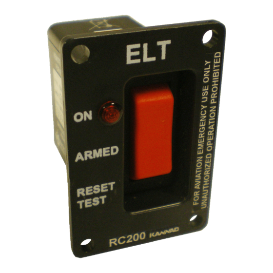
REMOTE CONTROL PANELS RC200 / RC200 NVG 3. Description A. General The RC200 or RC200-NVG remote control panels are designed to be installed in cockpits of aircraft to enable the pilots to control the ELT on board. The RC200 or RC200-NVG enable remote control of the primary functions of the KANNAD Emergency Locator Transmitters (Manual activation, Reset, Test) as well as visual monitoring. -
Page 7: Rcp Installation And Connection
(Refer to B. RC200 drilling mask, page 20). • Make the cut out. • Mark the 4 holes needed for the RC200 using the drilling mask or the RC200 as a guide. • Drill the 4 marked holes, diameter depending on rivet bush used. -
Page 8: Connection
- or a Programming Dongle, P/N S1820514-01; - or a Programming Dongle ASSY, P/N S1820514-06 (Programming dongle already fitted with a 6-wire bundle and a DIN-12 female connector). PAGE: 4 OCT 03/2022 © 2022 Orolia S.A.S. All rights are strictly reserved. -
Page 9: Connection With Din-12 Connector Or Programming Dongle
• Strap pins 4 and 5 of the female D-SUB 9-Pin connector; • Pin 4 (RESET/TEST) has to be connected to Pin A (RCP ON/RESET) of the ELT; PAGE: 5 OCT 03/2022 © 2022 Orolia S.A.S. All rights are strictly reserved. -
Page 10: Connection With Stopping Connector
- Put heat-shrinkables sleeves to protect the pins. On the long cable: Solder a standard DIN-12 male connector on ELT side: - KANNAD 406 AF COMPACT series (S1840501-xx) and INTEGRA PAGE: 6 OCT 03/2022 © 2022 Orolia S.A.S. All rights are strictly reserved. - Page 11 • Pin 2 (RCP BUZZER) has to be connected to Pin H (RCP BUZZER) of the ELT (only if an optional outside buzzer or external warning is used, PAGE: 7 OCT 03/2022 © 2022 Orolia S.A.S. All rights are strictly reserved.
-
Page 12: Connection With Programming Dongle Assy
On the RCP side: - KANNAD 406 AF COMPACT series (S1840501-xx) and INTEGRA ELTs (S185X501-XX) • Strap pins 4 and 5 of the female D-SUB 9-Pin connector; PAGE: 8 OCT 03/2022 © 2022 Orolia S.A.S. All rights are strictly reserved. - Page 13 ELT (only if an optional outside buzzer or external warning is used, Refer to § (4) Optional Outside Buzzer / Horn - Annunciator page Figure 5: Connection with programming dongle assy PAGE: 9 OCT 03/2022 © 2022 Orolia S.A.S. All rights are strictly reserved.
-
Page 14: Optional Outside Buzzer / Horn - Annunciator
- connect the DIN-12 connector (or programming dongle or programming dongle assy) to J1 of the ELT; • On the RCP side connect the female D-SUB 9-Pin connector to the male D-SUB 9-Pin connector. PAGE: 10 OCT 03/2022 © 2022 Orolia S.A.S. All rights are strictly reserved. -
Page 15: Acceptance Test Procedure
(Refer to D. RCP operational tests, page 15). 5. Working mode A. Controls The following elements are to be found on the RC200 remote control panels: 1. a 3-position switch (ON, ARMED, RESET & TEST); 2. a red visual indicator. -
Page 16: Monitoring
• 1 long flash during ELT transmission on 406 MHz. Self-test: (Refer to C. RESET & TEST, page 13). Refer to operation manuals of the ELTs for precise information on these modes. PAGE: 12 OCT 03/2022 © 2022 Orolia S.A.S. All rights are strictly reserved. -
Page 17: Operation
However, each self-test consumes energy from the battery. Should self-tests be carried out more often than the maximum allowed, the battery life-time of the ELT might be shorter than specified. PAGE: 13 OCT 03/2022 © 2022 Orolia S.A.S. All rights are strictly reserved. -
Page 18: Reset
ELT), the ELT transmission will stop for max. 50 seconds then start again. In this case, on the RCP: • The led is off for max. 50 seconds then flash again. PAGE: 14 OCT 03/2022 © 2022 Orolia S.A.S. All rights are strictly reserved. -
Page 19: Rcp Operational Tests
Check correct operation of RCP visual indicator by switching ELT and RCP as described in the following sequential procedure, Figure 11: RCP visual indicator operation (with ELT switch in the «ARM» position). Figure 11: RCP visual indicator operation PAGE: 15 OCT 03/2022 © 2022 Orolia S.A.S. All rights are strictly reserved. -
Page 20: Technical Characteristics
(3) Weight • Approx. 35 gr. (0.077 lbs), 55 gr. (0.121 lbs) with mounting tray, screws and connector B. Electrical Characteristics • Visual indicator: from ELT power supply. PAGE: 16 OCT 03/2022 © 2022 Orolia S.A.S. All rights are strictly reserved. -
Page 21: Electrical Interface
RCP BUZZER Mating connector BUZZER GND BUZZER Back face of inserts RCP RESET RCP ON EXT WARNING 1 A/C DC POWER BUZZER OUT BUZZER RCP COMMON RCP LED PAGE: 17 OCT 03/2022 © 2022 Orolia S.A.S. All rights are strictly reserved. -
Page 22: Compatibility List
AF-H INTEGRA (ER-N) S1852501-03 3 or 4 AP-H INTEGRA (ER) S1854501-02 3 or 4 AP-H INTEGRA S1854501-01 3 or 4 AP-H INTEGRA (ER-N) S1854501-03 3 or 4 PAGE: 18 OCT 03/2022 © 2022 Orolia S.A.S. All rights are strictly reserved. -
Page 23: Schematics And Diagrams
INSTALLATION MANUAL / USER MANUAL REMOTE CONTROL PANELS RC200 / RC200 NVG 9. Schematics and diagrams A. RC200 Outline dimensions PAGE: 19 OCT 03/2022 © 2022 Orolia S.A.S. All rights are strictly reserved. -
Page 24: Rc200 Drilling Mask
INSTALLATION MANUAL / USER MANUAL REMOTE CONTROL PANELS RC200 / RC200 NVG B. RC200 drilling mask PAGE: 20 OCT 03/2022 © 2022 Orolia S.A.S. All rights are strictly reserved. -
Page 25: Wiring Diagram For Kannad 406 Af-Compact Serie (3-Wire) And Integra Elts 3 Or 4-Wire
INSTALLATION MANUAL / USER MANUAL REMOTE CONTROL PANELS RC200 / RC200 NVG C. Wiring diagram for KANNAD 406 AF-COMPACT Serie (3-wire) and INTEGRA ELTs 3 or 4-wire PAGE: 21 OCT 03/2022 © 2022 Orolia S.A.S. All rights are strictly reserved. -
Page 26: Wiring Diagram For Other Kannad 406 Elts (4 Or 5-Wire)
INSTALLATION MANUAL / USER MANUAL REMOTE CONTROL PANELS RC200 / RC200 NVG D. Wiring diagram for other KANNAD 406 ELTs (4 or 5-wire) PAGE: 22 OCT 03/2022 © 2022 Orolia S.A.S. All rights are strictly reserved. - Page 28 Distributed by Manufactured by Orolia S.A.S Z.I. des Cinq Chemins CS10028 56520 GUIDEL - FRANCE Phone: +33 (0) 2 97 02 49 49 Web: https://www.orolia.com DMA00514F...
Need help?
Do you have a question about the RC200 and is the answer not in the manual?
Questions and answers