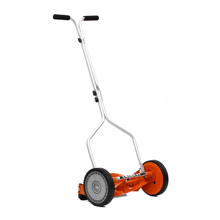
American Lawn Mower Co. 1204-14, 1304-14 - Lawn Mower 14" Manual
- Owner's manual (9 pages) ,
- Operation and assembly instructions (8 pages) ,
- Owner's manual (12 pages)
Advertisement
SAFETY RULES

- Read all instructions in this manual before using mower.
- Inspect your lawn for any debris or foreign objects and remove them before mowing.
- Never place your hands, fingers or feet inside the reel. Although not powered by motor, when the wheels turn, the reel cuts.
- Never mow when the grass is wet enough to be slippery.
- Don't place your hands or feet near a moving part of the mower.
- Don't operate the mower while barefoot orwearing sandals.
- Walk slowly, never run. Always be sure of yourfooting when operating the mower.
- Never intentionally strike or ram trees, fences, etc. This can cause injuries or severely damage the mower.
- Remember that this mower is a precision piece of lawn care equipment. Treat it as such by exercising caution when using it.
- Make sure your mower is in safe operating condition. Don't attempt to operate the mower if it is damaged; have it repaired first.
California Proposition 65 Warning:
This product contains chemicals known to the State of California to cause cancer, birth defects or other reproductive harm.
How to Assemble
Handle
Enclosed in carton are the mower handle parts (2 upper handlebar pieces and 2 lower pieces) and hardware package (for contents, see back cover).
- Lay out the parts of the handle as shown in figure 1.

- Fasten the 2 lower handle pieces to the upperportion of the handle using the 2 - M6X55 bolts and wing nuts.
- Fasten the 2 upper handlebar pieces togetherusing the M6X45 bolt and wing nut.
- Lubricate the inside of the 2 handle grips withsoapy water (for easier application) and slide onto the handle.

Attaching the handle to the unit
DO NOT attempt to attach the handle to the bolts on the roller assembly at the rear of the mower. This is incorrect! (refer to figure 3)

As you follow the instruction below, refer to figure 2 for more information.

- After assembling the handle, fit the holes atthe end of the lower portion of the handle on the left and right side, over the short posts extending out from the side plates.
- When the handle is in place over the posts, snap the "E" rings onto the slotted posts on both sides to prevent the handle from coming off.
Usage and Care
Minor cutting height adjustments
The cutting height on these units can be adjusted simply by adjusting the roller assembly. Model 1204-14 can be adjusted from 1/2" (1.27 cm) to 1 3/4" (4.45 cm) and Model 1304-14 can be adjusted from 1" (2.54 cm) to 2 1/4" (5.72 cm). Keep in mind that the same adjustment must be performed on both sides of the mower.
As you follow the instructions below, refer to figure 4 for more information.

- To achieve the lowest cutting position, loosenand remove the nuts on both sides of the roller assembly.
- Position the bolt through the bottom hole ofthe plastic roller bracket and the top hole of the mower side plate. Retighten nuts on both sides.
- To achieve the highest cutting position, loosenand remove the nuts on both sides of the roller assembly.
- Position the bolt through the top hole of theplastic roller bracket and the bottom hole of the mower side plate. Retighten nuts on both sides.
Other cutting heights can be obtained by positioning the bolts through other hole locations.
Blade adjustment
The blades have been preadjusted before leaving the factory
Misalignment can occur resulting in blades that are too loose or too tight. If this happens, you will notice a rough, uneven cut or a hard pushing mower.
All adjustments are made from the rear of the mower (opposite from the bar with the logo decal). Each end of the cutting bar can be adjusted separately.
As you follow the instructions below, refer to figure 5 for more information.

- The cutting bar blade (located under the reel)pivots. The front screws move the cutter bar away from the blades, while the rear screws move the cutter bar toward the blades.
- Adjusting the screws is a very sensitive pro-cedure. 1/16th of a turn is considered a major adjustment.
- Before tightening one adjusting screw, besure to loosen the opposing screw an equal amount.
Loosening the blades
The cutting bar blade must be moved further from the cutting reel.
- Loosen both back screws equally by turning them counterclockwise.
- Tighten both front screws equally by turning them clockwise.
Tightening the blades
The cutting bar blade must be moved closer to the cutting reel.
- Loosen both front screws equally by turning them counterclockwise.
- Tighten both back screws equally by turning them clockwise.
Checking adjustments
- Turn mower upside down.
- Insert piece of paper (i.e., writing or newspaper) between the cutter bar and the reel blades, and carefully turn the reel blades by hand.
All blades should slice the paper evenly the entire length of the cutter bar while the reel turns smoothly.
If the mower has an intermittent cut, adjustment should be made to the appropriate side of the blades to attain proper cutting action.
General care
Minimum care is required to assure smooth operation of your mower.
- To avoid damage to the mower or cuttingblades, keep the area to be mowed free from any debris.
- We suggest a routine application of oil orlubricant (i.e. WD-40). This should be applied to all cutting surfaces, the cutting reel axle shaft and wheels.
Sharpening the cutting blades
When the mower is properly lubricated and adjusted, sharpening should not be necessary for several years. However, the following steps will allow you to do the procedure yourself at relatively little expense.
- Remove the "E" rings, wheels and pinionfrom both sides of the mower (refer to figure 6).
![]()
- Remove both pawls from the rectangularslots in reel shaft and reverse their positions (refer to figure 7).
![]()
- Reverse the placement of the pinion gears.
- Place the left pinion on the reel shaft. Replace the wheels and "E" rings.
- Spread a thin layer of lapping compound onthe front edge of the reel blades.
- Adjust the cutter bar blade so it has light butfirm contact with the reel blades across the full width of the cutter bar (refer to figure 8).
![]()


Do not overtighten the adjusting screws, as this could damage the cutter bar. Both screws must be tight on the final adjustment.
- Push the mower backward on a smooth sur-face (such as a sidewalk or paved driveway). Continue to do this until the reel blades rotate relatively free and front edge of the cutter bar blades are polished.
- Remove wheels; reverse pinions and pawl ison the right.
Clean any grinding compound or debris from the cutter bar blades, reel blades, pinion and pawl.
Lubricate axle and pinion with a light film of wheel bearing grease and replace wheels and "E" rings.
NOTE: It is recommended to use an industrial or valve lapping compound between 100-240 grit. This is usually available at an industrial or automobile supply store. If professional sharpening is required, consult your local yellow pages for lawn mower repair services.
How to Order Parts
Specify the following information when ordering parts:
- Complete model number (found on the identification decal on the rear of the cutter bar).
- Color of the parts you are ordering.
- Cutting width of your unit.
If you are uncertain of the number of the part to be replaced, you can make sure to receive the exact part(s) you need by mailing the broken part(s) prepaid to the factory along with your order. Be sure that when you are sending parts to enclose your name, address and telephone number in the package.
ALL PARTS ARE SOLD FACTORY DIRECT. MINIMUM CHARGE FOR ANY ORDER IS US$2.00 EXCLUDING SHIPPING. ALL SHIPPING CHARGES ARE THE RESPONSIBILITY OF THE PURCHASER.

Some dust and debris created by the use of this tool could contain chemicals known to the State of California to cause cancer and birth defects or other reproductive harm. Some examples of these chemicals are:
- chemicals in fertilizers
- compounds in insecticides, herbicides and pesticides
- arsenic and chromium from chemically treated lumber.
Your risk from exposure to these chemicals varies, depending on how often you do this type of work. To reduce your exposure, work in a well-ventilated area and with approved safety equipment, such as dust masks that are specially designed to filter out microscopic particles.
Product Parts


Parts Nos & ID Guide


Customer Responsibilities
Always use care when operating your lawn mower and keep clear of moving parts. Avoid striking or running into solid objects or debris in the area to be mowed. Be sure the mower is clear and follow a regular maintenance schedule in order to provide efficient and safe operation. A well-cared-for lawn mower will last long and operate more efficiently.
HANDLE ASSEMBLY HARDWARE PACKAGE

830 Webster St • Shelbyville, IN 46176 • 1-800-633-1501
www.americanlawnmower.com
www.earthwisetools.com
Documents / Resources
References

Download manual
Here you can download full pdf version of manual, it may contain additional safety instructions, warranty information, FCC rules, etc.
Download American Lawn Mower Co. 1204-14, 1304-14 - Lawn Mower 14" Manual
Advertisement


Need help?
Do you have a question about the 1204-14 and is the answer not in the manual?
Questions and answers