Table of Contents
Advertisement
Quick Links
Electrified Locks, Relays and Timers
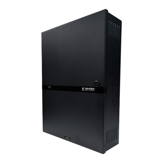
CX-PS600UL
POWER SUPPLY / CHARGER
THIS PACKAGE INCLUDES
1 - Power Supply Cabinet
1 - Instruction Manual
1. GENERAL DESCRIPTION
The CX-PS600UL power supply/charger series delivers a consistent 6-amp
supply current at 12/24V DC outputs. Housed in a robust steel enclosure,
it can accommodate one or two 12Ah lead acid rechargeable batteries. The
Camden CX-PS600UL meets the standards of ULC-S533, UL294, and ULC-
60839-11-1. Please note that this power supply is not designed to operate
fire notification devices, such as horns, strobes, or bells.
2. SPECIFICATIONS
Input
Output
Operating Temperature
Ripple
Maximum battery charging
current
3. KEY FEATURES
• Automatic Switch Over: The unit seamlessly transitions to
stand-by battery mode upon AC failure or when voltage drops below
72.5V AC, ensuring uninterrupted functionality.
• Battery Presence Detection: Within a brief span of just 10
seconds, the unit can detect if a battery is present.
• Temperature-Compensated Battery Charger: Integrated
into the system is a charger that adjusts for temperature, optimizing
battery life and performance. Important: This feature aligns with EN54-4
standards, but is not UL-evaluated.
• Battery Charger Monitor and Load Testing: The unit boasts
a robust monitoring system that conducts battery load tests every 48
hours, ensuring the battery's reliability and health.
2 - 2K2 Resistors
2 - Keys
120/240V AC, 50-60 Hz @ 2.5Amps
6 Amp continuous @ 12/24VDC
0 ˚C to 49 ˚C
50mVp-pmax
1.5Amps (not part of the max output
current rating) 13.8V/27.6V Nominal
13-3/8" W x 17-5/8" H x 4-1/2" D
(340mm x 449mm x 115mm)
• Battery Health Indicators: Equipped with indicators for battery
test results, battery reversal protection, low battery alerts at specific
voltages, and a disconnect feature at critical low voltages.
• Comprehensive Troubleshooting: Provides extensive
reporting for battery and charger issues (details available in the FAULT
TABLE).
• Visual AC Input Indication: A green LED illuminates when AC
input is active, serving as a clear visual cue.
• AC Fault Relay Contact: The unit includes a CMOS relay contact,
which activates upon AC failures.
• LED Display: The enclosure door features a multi-colored LED
display, including Green, Yellow, and Blue indicators.
• DC Output Indication: A blue LED, located both on the board and
the enclosure, signals the DC output status.
• Protection Measures: The system ensures the safety of its DC
output with built-in overload and short circuit protection mechanisms.
• Included Accessories: Every unit comes packaged with the
essential battery charging leads.
NOTE
This power supply should be installed in compliance with the National
Electric Code (NFPA 70) CSAC22.1, Canadian Electric Code, Part 1 and all
applicable Local Codes. Installation to be performed by qualified technical
personnel.
UL294 PERFORMANCE LEVEL
Destructive Attack
Level I
Line Security
Level I
Endurance Level
Level IV
Standby Power
Level III (when used with 12Ah/17.2Ah battery)
Page 1 of 8
Advertisement
Table of Contents

Summary of Contents for CAMDEN CX-PS600UL
- Page 1 12Ah lead acid rechargeable batteries. The reporting for battery and charger issues (details available in the FAULT Camden CX-PS600UL meets the standards of ULC-S533, UL294, and ULC- TABLE). 60839-11-1. Please note that this power supply is not designed to operate •...
- Page 2 CX-PS600UL Power Supply INSTALLATION INSTRUCTIONS 4. DIMENSIONS 13" [330mm] 13 3 8 " 5 1 2 " 5 1 2 " 4 1 2 " [340mm] [139mm] [139mm] [115mm] 7 5 8 " [194mm] 17 1 2 " 17 5 8 "...
- Page 3 CX-PS600UL Power Supply INSTALLATION INSTRUCTIONS 7. FAULT CONDITION & INDICATIONS FAULT LED-G LED-Y LED-R BATT RELAY AC RELAY LED-B Battery Reversed or Open Not Connected Battery Low Open Battery Disconnected Open The LED will flash rapidly five times, followed by a single Battery Test Failed flash every second.
- Page 4 CX-PS600UL Power Supply INSTALLATION INSTRUCTIONS 1. Install the power supply at your chosen location by utilizing the four mounting holes. Please note that this device is intended for indoor use only, within controlled environments. Avoid installing the power supply on exterior doors.
- Page 5 CX-PS600UL Power Supply INSTALLATION INSTRUCTIONS is reset. If JL is ON, the unit will follow the FIRE/ACP TRIGGER. Install PWX2K2 2.2K (EOLR) resistor at the Key Switch or Push Button to execute this operation. 4. Relay Output a) DC Fail: If one or more of the eight outputs fail due to overcurrent or short circuit, the DC Fail Relay will open. Connect this output to a monitoring device.
- Page 6 CX-PS600UL Power Supply INSTALLATION INSTRUCTIONS CX-PS600UL FIRE PROTECTIVE This Product must be installed in compliance with National Electrical CodeNFPA70, REGULATED POWER SUPPLY CHARGER and all applicable codes. CSA C22.1, UL/ ULC LISTED AS FOLLOWS: Safety Standard for Electrical Installations, UL294, CAN/ULC60839-11-1,CAN/ULC-S533 Canadian Electrical Code.
- Page 7 CX-PS600UL Power Supply INSTALLATION INSTRUCTIONS TYPICAL SUGGESTED APPLICATION WIRING DIAGRAM 2 OR MORE CX-PS600UL ACM8ECB CONNECTED IN CASCADE TO REVERSED KEY PAD ACP or FACP ACCESS CONTROL REV POL. POLARITY TERMINAL PANEL When any given switch is set to ON the output will not RELAY OUTPUT change on a Fire Point Trigger.Used to maintain power...
- Page 8 Tamper Switch Connection CX-PS600UL Power Supply INSTALLATION INSTRUCTIONS DICGU DICGU DICGU EOLR 1 TAMPER N/C EOLR 2 TAMPERS N/C DICGU DICGU EOLR DICGU EOLR 1 TAMPER N/O 2 TAMPERS N/O File: CX-PS600UL_Manual.indd Opening New Doors to Call: 1.877.226.3369 / 905.366.3377 File: CX-PS300UL_Manual.indd...
Need help?
Do you have a question about the CX-PS600UL and is the answer not in the manual?
Questions and answers