Table of Contents
Advertisement
Quick Links
Closed Cooling Water Circulator
Neocool Circulator
CF802-A
model
Instruction Manual
Second Edition
Thank you for choosing CF802-A Neocool Circulator
from Yamato Scientific Co., Ltd.
For proper equipment operation, please read and
become thoroughly familiar with this instruction
manual before use. Please store this document close
at your hands for future reference.
Yamato Scientific Co. Ltd.
Printed on recycled paper
Advertisement
Table of Contents
Troubleshooting

Subscribe to Our Youtube Channel
Summary of Contents for Yamato CF802-A
- Page 1 Neocool Circulator CF802-A model Instruction Manual Second Edition Thank you for choosing CF802-A Neocool Circulator from Yamato Scientific Co., Ltd. For proper equipment operation, please read and become thoroughly familiar with this instruction manual before use. Please store this document close at your hands for future reference.
- Page 2 CF units are for an external closed-loop circulation system such as evaporators. ● Circulation hoses are not included. Hoses and nozzles are available as options, ● prepare them according to the application.
-
Page 3: Table Of Contents
TABLE OF CONTENTS 1. SAFETY PRECAUTIONS ......................1 Explanation of Symbols ......................1 Symbol Glossary ........................2 Warnings and Cautions ......................3 Residual Risk Map ........................5 List of Residual Risks ........................ 6 2. COMPONENT NAMES AND FUNCTIONS ................... 8 External View .......................... - Page 4 Pump Performance Curve ....................... 35 13. OPTIONAL ACCESSORIES ..................... 36 List of Options ......................... 36 14. REPLACEMENT PARTS LIST ....................53 15. LIST OF HAZARDOUS SUBSTANCES ..................54 16. STANDARD INSTALLATION MANUAL ..................55...
-
Page 5: Safety Precautions
1. SAFETY PRECAUTIONS Explanation of Symbols... -
Page 6: Symbol Glossary
1. SAFETY PRECAUTIONS Symbol Glossary WARNING / CAUTION Danger!: Caution: Caution: General Blast Hazard Burn/Frostbite Hazard May Leak Water! RESTRICTION General Do Not Do Not Touch Restriction Disassemble ACTION General Action Connect Level Installation Disconnect Power Required Ground Wire Inspect Regularly... -
Page 7: Warnings And Cautions
1. SAFETY PRECAUTIONS Warnings and Cautions WARNING Install in a location free of flammables and explosives. Never install or operate the unit in a flammable or explosive gas atmosphere. This unit is NOT fire or blast resistant. Simply switching earth leakage breaker (ELCB) "ON (|)" or "OFF (O)"... - Page 8 1. SAFETY PRECAUTIONS Warnings and Cautions Handle power cable with care. ・Do not operate unit with power cable bundled or tangled. Operating unit with the power cable bundled or otherwise tangled, may cause power cable to overheat and/or catch fire. ・Do not modify, bend, forcibly twist or pull on power cable.
-
Page 9: Residual Risk Map
1. SAFETY PRECAUTIONS Residual Risk Map These figures indicate positions of caution labels. The numbers shown in the figure indicate the numbers listed in the "List of Residual Risks" in this manual. For details of individual residual risks, see the List of Residual Risks. 1, 3, 5, 6, 9, 11, 14 *Contact original dealer of purchase if the nameplates and caution labels have... -
Page 10: List Of Residual Risks
1. SAFETY PRECAUTIONS List of Residual Risks List of residual risks (instructions for risk avoidance) This list summarizes residual risks to avoid personal injuries during or related to the use of equipment. Be sure to fully understand or receive instructions on how to use, maintain and inspect equipment before starting operation. - Page 11 1. SAFETY PRECAUTIONS List of Residual Risks Daily inspection/maintenance Degree of Risk Relevant Protective measures taken by the user risks description page Be sure to turn OFF (O) ELCB and disconnect the Fire/ WARNING power cable before daily inspection and Electric shock maintenance.
-
Page 12: Component Names And Functions
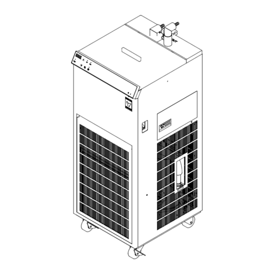
2. COMPONENT NAMES AND FUNCTIONS External View Earth leakage circuit breaker Reservoir Cover (ELCB) Rating label Serial number label Control panel (P.10) Condensation drain hose (included) Power switch Hose clamp (included) Drain hose Intake port Drain hose Drain plug Caster Drip tray (Please prepare separately) One-touch connector (L-type) -
Page 13: Circulation System
2. COMPONENT NAMES AND FUNCTIONS Circulation System Discharge Flow rate valve Rc3/8 (OUT) Return Rc3/8 (IN) Cooling coil Water reservoir ▼ ▼ Temperature sensor Circulation pump Drain plug Drain... -
Page 14: Control Panel
2. COMPONENT NAMES AND FUNCTIONS Control Panel ② ③ ⑩ ⑪ ⑤ ⑥ ⑦ ⑨ ④ ⑧ ① Panel item Description Power switch Turn ON/OFF power. ① Shows current temperature, temperature setting, user setting Temperature display ② items, etc. ③ Up key Press to increase or decrease set value, scroll items in user setting, and switch settings. -
Page 15: Pre-Operation Procedures
3. PRE-OPERATION PROCEDURES Installation Precautions Choose an appropriate installation site. DO NOT install unit: ・where installation surface is not completely level, not even or not clean. ・where flammable or corrosive gases/fumes may be present. ・where ambient temperature will exceed 35 °C, will fall below 5 °C, or will fluctuate. ・where liquid is assumed to splash on unit ・in excessively humid or dusty locations. - Page 16 3. PRE-OPERATION PROCEDURES Installation Precautions Take appropriate safety measures when installing. Implement appropriate safety measures for the installation environment. Unit may tip over or fall, causing injury or death during an earthquake or other unforeseen incident. Always connect a power cable to appropriate outlet. Connect power cable to a suitable facility outlet or terminal, according to the electrical requirements.
- Page 17 < Recommended Concentration > at -20 to 10 °C: Z1 60% * Do not use pure water as circulating water. The ready-to-use Raku-raku line of Nybrine solutions from Yamato Scientific is recommended. Contact original dealer of purchase for Raku-raku Nybrine solutions.
-
Page 18: Installation Procedures
4. INSTALLATION PROCEDURES Installation Procedure 1. Securing casters 1. Check that the four casters are uniformly placed on a flat location, and that unit does not wobble or tilt. Then lower the stopper levers to lock casters. Unlock Only two casters on the front of unit are equipped with stoppers. - Page 19 4. INSTALLATION PROCEDURES Installation Procedure 2. Circulation hose connection Connect hoses to the discharge port (OUT) and return port (IN) of the cooling water circulation system. Connection can be made with 10 mm O.D. rigid hose, or with 9 mm I.D flexible hose. See “List of Options”...
- Page 20 4. INSTALLATION PROCEDURES Installation Procedure 3. External circulation path Do not operate unit with the external circulation path shut. ・When a connection between unit and hose is made, connect to an external device as shown in the figure. Rotatable connector on the connection port allows free change in the direction. Adjust the direction so that the hose does not bend when connected to an external device.
- Page 21 4. INSTALLATION PROCEDURES Installation Procedure 4. Filling water reservoir Select circulating water according to "Preparation of circulating water" (P.13) 1. Open the lid and let circulating water flow into the reservoir Cooling coil until the cooling coil is immersed. 2. In this state, turn ON (|) ELCB and press the Power switch to run circulation pump and begin liquid circulation.
-
Page 22: Operation Procedures
5. OPERATION PROCEDURES Operation Procedure 1. Turn on power. 1. Turn ON (|) ELCB. 2. Turn ON (|) the Power switch. Temperature : Shows temperature reading following display the software version "V.○.○" Ref lamp : Flashing (goes off after about three minutes) indicates flashing. -
Page 23: User Setting
5. OPERATION PROCEDURES User Setting List of user setting items Press and hold for three seconds. User setting items will be shown. Select an item using the ∧∨ keys. Press again to edit the displayed item. While the user setting item is displayed, leaving unit without key operation for about two minutes will discard the unconfirmed changes, and the display reverts to the previous screen. -
Page 24: Calibration Offset
5. OPERATION PROCEDURES Calibration Offset Calibration offset is a function which can correct for any differences discovered between actual liquid temperature and the temperature displayed on the control panel. Offset function can correct to either the positive or negative side of the entire unit temperature range. ・Run unit at desired temperature. -
Page 25: Auto-Resume Function
5. OPERATION PROCEDURES Auto-resume Function Select recovery mode for the event of a power failure. OFF: Unit goes into idle at power recovery. (Default setting) ON: Unit automatically reverts to status just before power loss and begin operation once again from that point. -
Page 26: Selection Of Circulation Pump Operation At Temperature Upper Limit Alert
5. OPERATION PROCEDURES Selection of circulation pump operation at temperature upper limit alert Select the circulation pump operation for the time temperature upper limit alert (Hi) is issued and temperature reading exceeds 40 °C. OFF: Circulation pump will remain in idle. ON: Circulation pump begins running with the Pump key ON. -
Page 27: Led Brightness Setting
5. OPERATION PROCEDURES LED brightness setting Change the LED brightness of the control panel. The brightness can be set in 8 levels from 0 to 7. (Default setting: "3"). Enter user setting Turn ON (|) power and press for three seconds while temperature reading is on the screen. -
Page 28: Handling Precautions
6. HANDLING PRECAUTIONS Warnings and Cautions CAUTION DO NOT process explosive or flammable substances Never attempt to process explosives, flammables or any items which contain explosives or flammables. Fire or explosion causing serious injury or death may result. See "15. LIST OF HAZARDOUS SUBSTANCES"... - Page 29 6. HANDLING PRECAUTIONS Warnings and Cautions Circulation pump ・Do not operate with the circulating path completely closed. ・Make sure that the flow rate of circulating water keeps at least 1.5 L/min. ・Never operate circulation pump dry. Damage or malfunction may result. Operating unit without circulating water in the reservoir and circulation pump may cause seizure of the pump and/or other problems.
-
Page 30: Maintenance Procedures
7. MAINTENANCE PROCEDURES Inspection and Maintenance WARNING Be sure to disconnect power cable before conducting inspection and maintenance, unless otherwise necessary. Inspect and perform maintenance when circulating water is at room temperature. Never attempt to disassemble unit. CAUTION ... - Page 31 7. MAINTENANCE PROCEDURES Inspection and Maintenance Water reservoir maintenance Remove any foreign substances and debris from water reservoir as frequently as possible. Failure to do so may cause damage to circulation pump. Wear proper gloves when performing reservoir maintenance. Cleaning intake dust filter A clogged intake dust filter will degrade cooling performance and may result in refrigeration system malfunction.
- Page 32 7. MAINTENANCE PROCEDURES Inspection and Maintenance Fuse replacement Service outlet is equipped with overcurrent protection fuse. If overcurrent protection fuse has blown, eliminate the cause and replace with a spare. Fuse holder Fuse cap overcurrent protection fuse (2 A) 1. Turn OFF (○) ELCB and disconnect power cable. 2.
-
Page 33: Extended Storage And Disposal
Dispose of this unit in accordance with local laws and regulations. Dispose of or recycle this unit in a responsible and environmentally friendly manner. ・ Yamato Scientific Co., Ltd. strongly recommends disassembling unit, as far as is possible, in order to separate parts and recycle them in contribution to preserving the global environment. Major... -
Page 34: Troubleshooting
9. TROUBLESHOOTING Reading Error Codes Unit has a self-diagnostic function built into the CPU board and a separate safety device, independent of the CPU board. The table below shows possible causes and measures to take when safety device is triggered. [Error Codes] When an operational error or malfunction occurs, error code and temperature reading are alternately displayed on the control panel, and operation stops. -
Page 35: Troubleshooting Guide
9. TROUBLESHOOTING Troubleshooting Guide Symptom Possible causes Possible measures Display is blank Power supply failure Check power supply voltage when ELCB and (must be 115 V AC ±10%) the Power switch ELCB failure Replace relevant parts (call for service) are turned ON (|). -
Page 36: Service & Repair
10. SERVICE & REPAIR Requests for Repair Requests for Repair If abnormalities remain after confirming "Troubleshooting Guide", terminate operation, turn OFF (O) controller and ELCB, and disconnect power cable. Contact original dealer of purchase for assistance. The following information is required for all repairs. ... -
Page 37: Specifications
11. SPECIFICATIONS Product Name Closed Cooling Water Circulator Neocool circulator Model CF802-A System/circulating water Closed circulation/Nybrine, tap water, (over 10 °C) Operating ambient temperature range 5 to 35 °C Temperature setting range *1 -20 to 30 °C Temperature control accuracy ±1.0 °C... -
Page 38: Reference Data
12. REFERENCE DATA Cooling Capacity Curve The following graphs show cooling capacities and characteristics. Findings may vary with sample quantity, ambient temperature, individual differences and other factors. Use graph values as reference only. Analysis provisions ・Room temperature measurement: at the center of condenser inlet ・Power supply: 115 V AC Room temp. -
Page 39: Pump Performance Curve
12. REFERENCE DATA Pump Performance Curve The following graph shows the pump performance curve. Findings may vary with sample quantity, ambient temperature, individual differences and other factors. Use graph values as reference only. Analysis provisions ・Room temperature: 20 °C ・Power supply: 115 V AC Circulating water: 20 °C tap water Flow rate (L/min) Circulating water: 20 °C Nybrine Z1 (60%) -
Page 40: Optional Accessories
13. OPTIONAL ACCESSORIES List of Options A variety of optional accessories are available to suit the piping system of external device and for a wide range of uses. Contact original dealer of purchase for requests for options. Circulation connection components (fittings) Model Product Name Product... - Page 41 13. OPTIONAL ACCESSORIES List of Options Circulation connection components (hoses) Model Product Name Product Description Contents code Thermal insulation OCF12 Usable temperature range: Standard: hose 221581 -20 to 80 °C φ9 mm × φ13 mm × 2 m 2 pcs (flexible) * No freezing of circulating water (insulation: 28 mm O.D.)
- Page 42 Model OCF84 Product code 281478 This option is to liquefy and recover solvent gases remaining in a concentration recovery process. Connect hose to OUT (atmosphere) side of a vacuum pump. Vacuum port Concentrating device Secondary trap Exhaust Vacuum pump CF802-A...
- Page 43 13. OPTIONAL ACCESSORIES Secondary trap ・Packing List Part ① Glass container, capacity 1L (recovery volume 0.5L) ② Glass-stopper ③ Glass container holder ④ Mounting hardware ⑤ Observation window cover ⑥ Fixing plate ⑦ Vacuum nozzle (10 mm O.D.) ⑧ Fixing screw ⑨...
- Page 44 Secondary trap ・Instructions (1) Connect CF802-A and a cooling condenser with an optional circulation hose. See “List of Options” Circulation connection components (hoses) (P.37). * See “2. Circulation hose connection”(P.15) in CF802-A instruction manual for details. Rotatable connector on the connection port allows free change in the direction.
- Page 45 13. OPTIONAL ACCESSORIES Secondary trap (4) Fit ⑥Fixing plate into the notches on both sides of ④Mounting hardware, and fix them with ⑧Fixing screw. Insert into the notch and fasten with the screw. ⑧Fixing screw (both sides) ⑥Fixing plate ⑥Fixing plate ⑧Fixing screw ⑥Fixing plate ⑧Fixing screw...
- Page 46 13. OPTIONAL ACCESSORIES Secondary trap (6) Install ①Glass container in the reservoir of CF802-A. Glass container will come floating with buoyancy. Always hold the container by hand, and push it in with ③Glass container holder. Turn ③Glass container holder 90 degrees and secure it with the hooks.
- Page 47 To vacuum port Vacuum hose (sold separately) Hose (sold separately) Concentrating device To exhaust equipment Vacuum pump CF802-A Vacuum pump nozzle Hose connection port ②Glass-stopper Vacuum * External water bath should be pump positioned above the top of CF802-A unit CF802-A...
- Page 48 Vacuum pump nozzle Stop cock Vacuum hose (sold separately) To exhaust equipment Glass-stopper hose connection Vacuum pump * External water bath should be Vacuum hose positioned above the top of (sold separately) CF802-A unit Vacuum reaction vessel, etc. CF802-A...
- Page 49 13. OPTIONAL ACCESSORIES Secondary trap ・Handling Precautions ・ Stop the vacuum pump immediately when the concentrating operation is finished. The recovered solvent may evaporate again. ・If the liquid recovered by Secondary trap is stored more than adequate level, the internal pressure is applied to the exhaust path of the vacuum pump, resulting in equipment malfunction.
- Page 50 13. OPTIONAL ACCESSORIES Secondary trap Optional parts for Secondary trap Model Product Name Description Contents Product code One-touch ORE33 GL14, 10 mm O.D. 2 pcs Necessary when using connector 255743 thermal insulation hose Material (wetted part): (rigid)(281475) Polypropylene φ5/16 ×φ9/16 × 1.5 m 1 pc Tygon tubing LT00040100...
- Page 51 13. OPTIONAL ACCESSORIES List of Options Seal lid for External Open Connection Model OCF86 Product code 281479 This option allows to make a circulation connection to an open circulation path such as a water bath. ・Packing List Part ① Seal lid (with O-ring) ②...
- Page 52 (1) Change the fitting for the return connection with the return piping unit. ③Return piping unit (2) Connect circulation hoses to an open water bath. Be sure that circulation lines are the minimum required lengths. * External water bath should be positioned above the top of CF802-A unit...
- Page 53 Seal lid for External Open Connection (3) Close the flow rate valves of both discharge and return ports, and pour circulating water in the open water bath and the reservoir of CF802-A. (4) Push the lid in the opening on top of unit.
- Page 54 13. OPTIONAL ACCESSORIES Seal lid for External Open Connection (7) Press the Pump key to stop the pump and add circulation water to the appropriate level. With the flow rate valve open, remove silicon plug and the water level of the reservoir will gradually increase.
- Page 55 13. OPTIONAL ACCESSORIES List of Options External interlock input terminal Model OCF98 Product code 281485 This function is to start and stop cooling operation + circulation operation, or only circulation operation of unit by external control input (no-voltage a contact input). ・Terminal block placement On the back of unit External interlock input terminal...
- Page 56 13. OPTIONAL ACCESSORIES External interlock input terminal ・Setting instructions Make settings for external interlock function (int) in the user setting. OFF: Enables the Run/Stop key (cooling operation) and the Pump key (circulation operation) (Default setting) Cir: Enables the Run/Stop key (cooling operation), and disables the Pump key (circulation operation).
-
Page 57: Replacement Parts List
14. REPLACEMENT PARTS LIST Part name Part code Standard One-touch connector LT00039314 R3/8 (L-type) 10 mm O.D. connectors for Hose nozzle LT00039316 flexible hose with 9 mm I.D. 290 × 315mm Intake dust filter CF80243100 Front air intake Drain plug CF80241060 For 16 mm I.D. -
Page 58: List Of Hazardous Substances
15. LIST OF HAZARDOUS SUBSTANCES Never attempt to process explosives, flammables or any items which contain explosives or flammables. ①Nitroglycol, Glycerine trinitrate, Cellulose Nitrate and other explosive nitrate esters ②Trinitrobenzen, Trinitrotoluene, Picric Acid and other explosive nitro compounds ③Acetyl Hydroperoxide, Methyl Ethyl Ketone Peroxide, Benzoyl Peroxide and other organic peroxides ④Metallic Azide, including Sodium Azide, etc. -
Page 59: Standard Installation Manual
16. STANDARD INSTALLATION MANUAL Install this equipment according to following format (check options and special specifications separately). Charged Personnel or Installation Installation Model Serial Number Company Name for Judgment Date proved by Installation № Item Implementation method Chapter No. & Reference page of Judgment instruction manual Specifications... - Page 60 Yamato Scientific Co., Ltd. assumes no responsibility for malfunction, damage, injury or death, resulting from negligent equipment use. Never attempt to disassemble, repair or perform any procedure on CF802-A Neocool Circulator which are not expressly mandated by this manual. Doing so may result in equipment malfunction, serious personal injury or death.
Need help?
Do you have a question about the CF802-A and is the answer not in the manual?
Questions and answers