Table of Contents
Advertisement
Quick Links
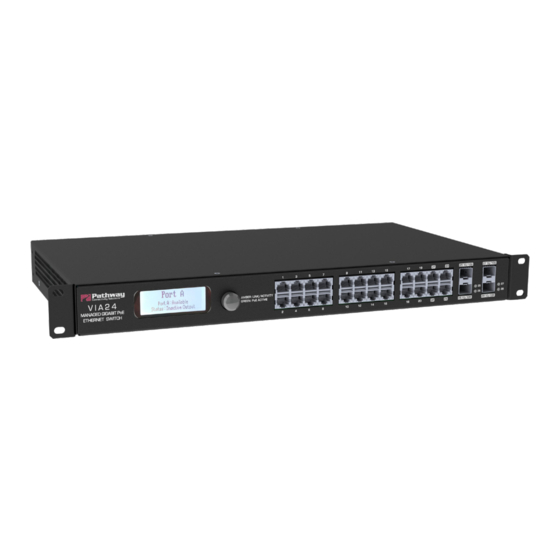
OVERVIEW
VIA™ Gigabit Ethernet Switches are designed for live
entertainment Ethernet systems, including audio, video and DMX-
over-Ethernet networks. This guide covers models PWVIA RM P24
RJ45 SFPSLOT POE
VIA Ethernet Switches are intended specifically for signal routing
between Pathport DMX-over-Ethernet gateways, or similar
equipment, and Ethernet-aware lighting and audio control products,
such as consoles and controllers and end equipment. A VIA is a
routing device and is not a source of the control protocols or the
data being passed. Switches only provide management control
over the data path.
The PWVIA RM P24 family is easily configured and upgraded
using the freely available software tool, Pathscape. They are also
configurable using the Front Panel UI, which consists of the LCD
and rotary pushbutton encoder.
CONNECTIONS
POWER
Connect the switch to an AC input between
50 or 60 Hz,
with included IEC power cable
ETHERNET
All network wiring should follow standard Ethernet rules and be
installed by a qualified person. As part of the installation, all wiring
should be certified under the TIA/EIA-568 standard.
Pathway recommends the use of manufactured rather than hand-
terminated cables.
POWER-OVER-ETHERNET (PoE)
VIA models PWVIA RM P24 RJ45 SFPSLOT POE feature an
integrated 170W PoE supply for powering compatible external
devices compliant with 802.3af.
SFP+ PORTS
Model PWVIA RM P24 RJ45 SFPSLOT POE have four SFP+
compatible ports on the front of the device. These require the user
to provide an SFP(1G) or SFP+(10G) fiber transceiver to allow
connection to fiber networks. Available Pathway Accessories are
listed on page 3 of this document. For short distances, Direct Attach
Copper (DAC) cables may also be used on these ports.
Part No. 912-00432-001 Rev. A
VIA Ethernet Switches
PWVIA RM P24
100 and 240VAC, either
STATUS INDICATORS
PoE
Solid green indicates PoE is active on the Port.
Link/Act
Amber. Intermittent blinking indicates valid link to
other device. Off indicates link is down.
Fiber Port
Green. Intermittent blinking indicates valid link to
LEDS
other device. Solid red indicates incompatible fiber
transceiver.
LCD
Will light up when using the front encoder knob. When
Backlight
set to Identify mode using Pathscape, the backlight
will flash.
INSTALLATION
Disconnect all power before proceeding with installation.
Securely mount device to rack unit, if applicable. Connect the AC
input. The VIA will boot up, which may take 60 seconds.
Attach required network cables to RJ45 ports. Connect the fiber
module(s), if used.
Choose the Security Mode from the front panel using the encoder
knob.
Security Mode
Wait for Pathscape to Secure
Local Configuration Only
Disable Security
If adding to a Security Domain in Pathscape, no input here is
needed. Open Pathscape on a PC on the same network as the
VIA and add the switch to a Security Domain.
If using the VIA from the front panel only, select Local Configuration
Only mode. The device will only be configurable from the Front
Panel, configuration from Pathscape is disabled although you may
read properties in Pathscape (Read Only mode).
If opting out of Security features, select Disable Security. The
device will be configurable using the front panel or using Pathscape
on the network, even by unauthorized parties.
The system is now ready for configuration and testing.
© 2021 Acuity Brands, Inc. • One Lithonia Way, Conyers GA 30012
Phone: + 1 866 617 3074 www.pathwayconnect.com
Installation
Guide
02/01/23
Advertisement
Table of Contents

Related Manuals for pathway PWVIA RM P24


Summary of Contents for pathway PWVIA RM P24
- Page 1 Amber. Intermittent blinking indicates valid link to over the data path. other device. Off indicates link is down. The PWVIA RM P24 family is easily configured and upgraded Fiber Port Green. Intermittent blinking indicates valid link to using the freely available software tool, Pathscape. They are also LEDS other device.
- Page 2 If using Pathscape to configure your network, you must decide on your networking scheme. Pathway devices ship from the factory with a unique IP address staring with 10.x.x.x with a subnet of 255.0.0.0. For new network systems, set your computer’s wired IP address to 10.0.0.x where x is a free address, and a subnet mask of 255.0.0.0.
- Page 3 Installation VIA Ethernet Switches Guide PWVIA RM P24 STANDARDS COMPLIANCE PHYSICAL • ANSI E1.31 sACN - Streaming ACN PPWVIA RM P12 RJ45EC POE • IEEE 802.3 Ethernet • Weight: 6.9 lbs (3.2 kg) • IEEE 802.3af Power-over-Ethernet (PoE-enabled models) •...
Need help?
Do you have a question about the PWVIA RM P24 and is the answer not in the manual?
Questions and answers