
Summary of Contents for Rotech SMARTY Series
- Page 1 IS131 Rev09 10/03/2022 SMARTY SERIES Swing gates automations INSTALLATION INSTRUCTIONS AND USER MANUAL T: +61 07 3205 1123 | E: info@rotech.com.au | www:rotech.com.au...
- Page 2 General safety precautions Failure to respect the information given in this manual may cause personal injury or damage to the device. This installation manual is intended for qualified personnel only. ROGER TECHNOLOGY cannot be held responsible for any damage or injury due to improper use or any use other the intended usage indicated in this manual. Installation, electrical connections and adjustments must be performed by qualified personnel, in accordance with best practices and in compliance with applicable regulations.
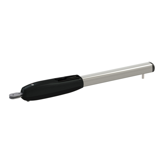
- Page 3 STANDARD INSTALLATION SMARTY RANGE DESCRIPTION Automatism SMARTY Control unit Key selector Flashing light Antenna External photocell Internal photocell Gate open mechanical stop...
- Page 4 DIMENSIONS 370 ( SMARTY5 - 5R5 - 4HS ) 520 ( SMARTY - 7R ) 1162 ( SMARTY - 5R5 - 4HS ) 1312 ( SMARTY - 7R ) All measurements are expressed in mm unless otherwise indicated. WARNING According to the legislation in force and for safety purposes, if the gate length exceeds 2.5 m with normal wings, 2 m with full wings and if its height exceeds 2 m, it is recommended to use an electric lock.
-
Page 5: Technical Data
TECHNICAL DATA SMARTY7 SMARTY7R USAGE TYPE CONDOMINIUM REVERSIBILE MOTOR TYPER BRUSHLESS MOTOR POWER SUPPLY RATED POWER °C WORKING TEMPERATURE -20°C +55°C JOGGING INTENSIVE USE PROTECTION RATING OPERATOR WEIGHT 12,2 13,2 35 ÷ 50 90° OPENING TIME WORKING SPEED 1,6 ÷ 1 cm/s 600 ÷... -
Page 6: Preliminary Checks
PRELIMINARY CHECKS SMARTY 7 / SMARTY 7R (Corsa massima/Max run = 520 mm) C (max) D (max) α° 1180 98° 1180 97° 1180 96° 1180 95° 1180 93° 1180 102° 1180 100° 1180 93° 1180 106° 1180 94° PRELIMINARY CHECKS •... - Page 7 BRACKETS FASTENING FASTENING BRACKETS 1. Fasten the rear bracket in a perfectly level position and in accordance with the installation measurements indicated in paragraph 6. • For masonry/cement pillars, use the specific masonry brackets with suitable anchor bolts and screws. •...
- Page 8 INSTALLATION DRIVE UNIT INSTALLATION • The SMARTY piston may be installed on the right or left hand side. • Fasten the piston to the rear bracket and to the front bracket, lubricating the pivot points. • Move the gate manually and check that it moves smoothly throughout its entire travel without impediment or friction.
- Page 9 MECHANICAL STOPS ADJUSTMENT Stringere con forza Tighten strongly Stringere con forza Tighten strongly Fig. 1 Fig. 2 Use the internal mechanical stops in the piston as a supplementary safety measure in addition to the mechanical stops of the gate. WARNING: the mechanical stops have become loose inside the piston. Even if not used, they must always be securely fastened.
-
Page 10: Electrical Connections
ELECTRICAL CONNECTIONS 3 x 2.5 mm² A switch or an omnipolar cut-off switch with a contact opening of at least 3 mm must be installed on the mains power line. Ensure that an adequate residual current circuit breaker with a threshold of 0.03 A and a suitable over-current cut-out are installed ahead of the electrical installation in accordance with best practices and in compliance with applicable legislation. - Page 11 ABSOLUTE MAGNETIC ENCODER The encoder determines the precise position of the gate, and allows the controller to reacquire the position of the gate leaf immediately when the first command is received following a power failure or after the gate is unlocked. For SMARTY REVERSIBLE: the encoder is already installed in the factory by ROGER TECHNOLOGY.
-
Page 12: Periodical Maintenance
PERIODICAL MAINTENANCE NOTE: Only use original spare parts when repairing or replacing products. The installer must provide the user with complete instructions for using the motorised door or gate in automatic, manual and emergency modes, and must deliver the operating instructions to the user of the installation upon comple- tion. - Page 13 General safety precautions for the user These precautions are an integral and essential part of the product and must be supplied to the user. Read them carefully since they contain important information on safe installation, use and maintenance. These instructions must be kept and forwarded to all possible future users of the system. This product must only be used for the specific purpose for which it was designed.
Need help?
Do you have a question about the SMARTY Series and is the answer not in the manual?
Questions and answers