
Subscribe to Our Youtube Channel
Related Manuals for Gatekeeper AI282s


Summary of Contents for Gatekeeper AI282s
- Page 1 AI282s and SP25 Stop Arm Camera System Installation Guide Document Ref. No. : DN3585 Version No. : V1.0.4 Document Date : August 2023...
-
Page 2: Table Of Contents
3 Mount Location of AI282s and SP25 ....................4 4 AI282s Calibration Using G4Connect ....................5 5 Setup AI282s / SP25 Alarm Recording in the DVR ............... 8 6 Setup Wireless Download for Alarm Video .................. 12 7 Image of AI282s and SP25 ........................ 15 8 Product Dimensional Drawing ...................... -
Page 3: Overview
The SP25 camera is a high-performance license plate reading camera that eliminates motion blur caused by vehicles traveling at speeds up to (60 mph / 100 kph). The AI282s camera utilizes Artificial Intelligence (AI) to detect vehicles as they enter a detection zone when the stop arm is deployed. -
Page 4: Mount Location Of Ai282S And Sp25
The bus has 0.5-meter (19.7 inches) clearance from ground to start of the bus frame. • Right side edge of the AI282s is in line with the stop arm. (Meaning the camera is just to • the left of the stop arm) -
Page 5: Ai282S Calibration Using G4Connect
2. Periodic cleaning of SP25 camera lens in required. 4 AI282s Calibration Using G4Connect This section describes how to calibrate the AI282s camera after it is installed on a bus. 1. Connect the AI282s v3 to G4Connect, go to Preview, click on ‘AI Calibration’. - Page 6 AI282s v3 and SP25 Stop Arm Camera System Install Guide 2. Select on ‘AI282’ for calibration. 3. Choose the corresponding channel of the AI282s camera, then click on ‘Calibration’.
- Page 7 AI282s v3 and SP25 Stop Arm Camera System Install Guide 4. Drag points to adjust the detection zone, then click on ‘Save’. Note1: Align the detection zone to cover the lanes where vehicles are to be detected. Note2: Each time the stop arm is deployed, the counter will start at 000, and count 1 for each violation detected (e.g., 001, 002, 003…).
-
Page 8: Setup Ai282S / Sp25 Alarm Recording In The Dvr
AI282s v3 and SP25 Stop Arm Camera System Install Guide 5 Setup AI282s / SP25 Alarm Recording in the DVR This section describes how to setup the AI282s camera via G4 Connect or ICD. If using an ICD, the steps are the same. - Page 9 AI282s v3 and SP25 Stop Arm Camera System Install Guide 4. Click on “Setup” in Linkage under Violation F, then select the corresponding channels of the AI282s and SP25. Set Post Recording to 30 seconds. 5. Click on “Save” after configurated the settings in Trigger and Linkage.
- Page 10 7. Set “Debounce Time” to 0 seconds to finish detection immediately when the stop arm is folded in. Note: For example, if the Debounce Time is set to 10 seconds, when the stop arm is folded in, AI282s continues to detect for 10 seconds. Any vehicle driving through the detection zone will cause an alarm.
- Page 11 8. Click on “Save” after configured settings in Trigger. Note: AI282s is set to record all the time and the SP25 should be set to record for alarm. When the AI282s is deployed and a vehicle entering the violation zone, both the AI282s and SP25 starts recording with a red record icon displayed on the screen of the ICD or G4Connect.
- Page 12 AI282s v3 and SP25 Stop Arm Camera System Install Guide 9. Navigate to Preferences -> Surveillance -> Record -> General to set Pre-recording time. Note: When a violation occurs, the prerecording is used to capture the incident. It records the evidence that the stop alarm is deployed promptly.
-
Page 13: Setup Wireless Download For Alarm Video
AI282s v3 and SP25 Stop Arm Camera System Install Guide 6 Setup Wireless Download for Alarm Video This functionality requires the vehicle to be able to connect either via cellular or Wi-Fi to Gatekeepers G4E wireless server. If wireless connectivity to the vehicle is not available this functionality is not available. - Page 14 AI282s v3 and SP25 Stop Arm Camera System Install Guide 3. Choose the corresponding BUS in Task. The following is an example to setup an auto downloading task. 4. Select Channels, then click on ”Save”.
-
Page 15: Image Of Ai282S And Sp25
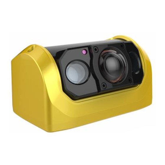
AI282s v3 and SP25 Stop Arm Camera System Install Guide 7 Image of AI282s and SP25 AI282s... -
Page 16: Product Dimensional Drawing
AI282s v3 and SP25 Stop Arm Camera System Install Guide SP25 8 Product Dimensional Drawing... -
Page 17: Appendix
AI282s v3 and SP25 Stop Arm Camera System Install Guide Appendix Product Specification AI282s v3 Specifications Video Image Sensor 1/3″ 2.0 mega pixel progressive scan CMOS Resolution 1080p (1920 x 1080) 720p (1280 x 720) D1 (720 x 480) 165° horizontal and 85° vertical Lens 1.8mm... - Page 18 AI282s v3 and SP25 Stop Arm Camera System Install Guide Network Protocol TCP/IP, HTTP, DHCP, NTP, FTP Configuration Built-in web server Power Power Supply 12V POE Physical Dimensions 3.93” (100mm) width x 2.36” (60mm) height Electrical Connector RJ 45 Environmental Operating Temperature -40°F to + 158°F (-40°C to +70°C)
- Page 19 AI282s v3 and SP25 Stop Arm Camera System Install Guide Weight: 1.1 lbs, (500g) Electrical Connector RJ 45 Recommended Add-Ons High Overview External Camera Power Voltage POE (DC12V Nominal) Consumption 9.0W / IR ON 3W / IR OFF Environmental Operating Temperature...
Need help?
Do you have a question about the AI282s and is the answer not in the manual?
Questions and answers