
Related Manuals for TRM LWH 1500

Summary of Contents for TRM LWH 1500
- Page 1 Handheld Laser Welding System (LWH 1500 / LWH 2000) Version No.:LWH 15+20M-S-TRM...
- Page 2 Disclaimer Disclaimer The company reserves all copyrights. You may not copy, reproduce, transmit, store in a retrieval system or adapt this publication, in any form, in any media or by any means, without the prior written permis- sion of the company, except as allowed under applicable copyright laws. Permitted copies shall bear the same copyright and proprietary notices which were contained on the original version。...
- Page 3 Disclaimer Export, Import and Customs Control Compliance (For CN Products Only) The company is committed to complying with U.S. and foreign export, import and customs require- ments. Export and re-export of lasers and other products manufactured by the company are subject to China and foreign laws and regulations, including the China Export Administration Regulations administered by the Department of Commerce, Bureau of Industry and Security.
- Page 4 This user guide should stay with the product to provide you and all future operators, users, and owners of the product with important operating, safety and other information. For product technical assistance, contact Customer Service of the company. TRM Technology, Inc #9, Huanbaosanlu, Xinbei District, Changzhou,Jiangsu, 213034,China. Tel:+86(519)-8577-7780 www.trm-welding.com...
-
Page 5: Table Of Contents
contents contents 一、Overview 1.1 Introduction 1.2 Intended use 1.3 Certification 1.4 Models Covered 1.5 Unpacking instructions 1.5.1 Delivery and Shipping 二、Safety and Compliance Information 2.1 Safety Information and Conventions 2.2 Government Security Requirements and Features 2.2.1 Compliance with regulatory standards 2.2.2 Class A Digital Device 2.2.3 Functional Safety 2.2.4 Laser Classification... - Page 6 contents 4.2 Add water and exhaust 4.2.1 Water 4.2.2 Exhaust and drainage 4.3 Product use 4.3.1 Inspection before commissioning 4.3.2 Controller Panel Introduction 4.3.3 Boot display 4.3.4 Controller Temperature Display 4.4 Controller Parameter Setting 4.5 Maintenance 4.5.1 Dustproof in summer 4.5.2 Anti-freeze in winter 4.6 Routine maintenance 4.7 Circuit diagram...
-
Page 7: 一、Overview
Overview Overview 1.1 Introduction The company introduces a new type of industrial Infrared fiber laser welding system that consists of a handheld optical output head. Its maximum continuous wave power≥1500W(1500w series), ≥2000W(2000W series). The company fiber laser welding system has been designed and tested with safety in mind. By following this User’s Guide and applying sound laser safety practices, it can be a safe and reliable device. -
Page 8: Intended Use
Upon receipt of the unit, please inspect the packaging and parts for any damage during shipping. If damage is apparent, please contact our customer service department immediately. 1.4 Models Covered Laser welding models covered in this document include: ・ LWH 1500 ・ LWH 2000 Operating Instruction... -
Page 9: Unpacking Instructions
Overview 1.5 Unpacking instructions If the packaging shows any signs of external damage, inspect the unit for damage and notify the shipping agent immediately.When you take the unit out of the box, take extra care to ensure that the fibers are not broken or damaged.A comprehensive packing list is included with the system documentation. - Page 10 Overview Figure 1-2. Transport Monitoring - Tilt and Shock Operating Instruction...
- Page 11 Overview This red indicator indicates a possible dange ・ Check the laser for damage immediately after delivery. ・ If damage occurs, notify the company and the shipping company in writing. The company recommends the following when unpacking: ・Use only suitable tools and aids ・Follow all steps to ensure safe unpacking of product ・...
-
Page 12: 二、Safety And Compliance Information
Safety and Compliance Information Safety and Compliance Information 2.1 Safety Information and Conventions To ensure the safe operation and optimal performance of the product, follow all warnings in the product User Guide. Safety precautions must be observed during all phases of operation, maintenance, and service Operators must adhere to these recommendations and apply sound laser safety practices at all times. -
Page 13: Government Security Requirements And Features
Safety and Compliance Information 2.2 Government Security Requirements and Features 2.2.1 Compliance with regulatory standards EMC emission: EN 55011:2009+A1:2010 EMC Immunity: EN 61000-6-2:2019/EN 61000-6-4:2019 Electrical Safety: EN 61010-1:2010 Laser Safety: EN 60825-1:2014 Table 2-B. Regulatory Standards This unit is designed to meet the regulatory standards listed. It will be verified by self-test in the near future. 2.2.2 Class A Digital Device This equipment is tested and complies with the limits for a Class A digital device, pursuant to part 15 of the FCC Rules and Canadian ICES-003 when marked as such on the product. -
Page 14: Functional Safety
Safety and Compliance Information 2.2.3 Functional Safety EN ISO 13849-1:2008+A1:2009 Cat.3/PL d。The following safety features are only implemented in hardware: ・Shutdown initiated by safety device: The safety electronics of the laser monitor the feed fiber 1 (fiber interlock). If the laser is firing and the feed fiber is disconnected or damaged from the docking device, the laser is powered off. -
Page 15: Laser Classification
Safety and Compliance Information 2.2.4 Laser Classification Governmental standards require that all lasers be classified according to their output power or energy and the laser wavelength. This product emits invisible laser radiation at or around a wavelength of 1080 nm. The total light power radiated from the optical output is greater than 1500 W average and greater than 2500 W peak per optical output port, depending on the model. - Page 16 Safety and Compliance Information Please wear suitable laser safety glasses when operating this device.The selection of appropriate laser safety eyewear requires the end user to accurately identify the range of wavelengths emitted from this product. If the device is a tunable laser or Raman product, it emits light in a range of wavelengths. End users should verify that the laser safety glasses used are capable of blocking light emitted by the device over its entire wavelength range.
-
Page 17: Device Safety Label Locations
Refer to Table 2-C for a description of all safety labels and their placement on the product. MAX.AVERAGE OUTPUT POWER: - 1500W(LWH 1500) - 2000W(LWH 2000) Figure 2-1. Laser Safety Banner Label... - Page 18 4. Laser Information Label - Class 4 IR Laser 5. Warning Label - Class 4 IR Laser AVOID EXPOSURE MAX AVERAGE OUTPUT POWER : DANGER -NVISIBLE LASER - 1500W(LWH 1500) RADIATION AVOID EYE OR SKIN VISIBLE AND INVISIBLE LASER - 2000W(LWH 2000) EXPOSURE TO DIRECT OR...
- Page 19 Safety and Compliance Information 6. Class 2M Red Guide Laser 7. Panel Label 8 Aperture Exposure Label - Weld Head LASER RADIATION DANGER -NVISIBLE LASER AVOID EXPOSURE DO NOT STARE INTO BEAM OR RADIATION AVOID EYE OR SKIN VISIBLE AND INVISIBLE LASER VIEW DIRECTLY WITH OPTICAL EXPOSURE TO DIRECT OR RADIATION IS EMITTED FROM...
- Page 20 4. Laser Information Label - Class 4 IR Laser IMPORTANT TO FOLLOW 5.Warning Label - Class 4 IR Laser MAX.AVERAGE OUTPUT POWER:1500W CW LWH 1500/2000W SAFETY INFORMATION WAVELENGTH RANGE:900-1200nm & THE USER GUIDE.FOR ACCESS: VISIBLE AND/OR INVISIBLE LASER RADIATION AVOID EYE OR SKIN EXPOSURE TO...
- Page 21 Safety and Compliance Information Figure 2-3 Label Placement – Output Weld Head Weld Head 8.Aperture Exposure Label - 9.Safety glass label SAFETY GLASSES MUST BE WORN Operating Instruction...
-
Page 22: Important Welding Specific Safety Information
Safety and Compliance Information Important Welding Specific Safety Information 2.3.1 Secondary Radiation Hazard Visible and Invisible Light Radiation Produced During Welding.The interaction between high power laser beams and target materials being welded may create plasmas that produce UV emissions and “blue light” which may cause conjunctivitis, photochemical damage to the retina and/or sunburn-like reaction to the skin. -
Page 23: Fire Hazard
Safety and Compliance Information 2.3.4 Fire Hazard The heat and sparks produced during welding are capable of starting a fire or causing an explosion. Laser welding should only be performed if the area is free of combustible materials Never weld on containers that have flammable or combustible material. If the container contents are unknown, you should assume they are flammable or combustible. -
Page 24: Gas Cylinder Safety
Safety and Compliance Information 2.3.6 Gas Cylinder Safety Gas cylinders may explode if damaged or placed nearby to the welding area causing injury and property damage. Gas cylinders should be shielded and located in areas where they cannot be struck or damaged.Place them away from sources of heat, sparks or flame, as well as deflection from laser beam. -
Page 25: General Safety Instructions
Safety and Compliance Information 2.4 General Safety Instructions If this device is used in a manner not specified in this document, the protection provided by the device may be impaired and the warranty will be voided. 2.4.1 Specular Reflections Often there can be numerous secondary laser beams produced at various angles near the laser output aperture. -
Page 26: Optical Safety
Safety and Compliance Information 2.4.3 Optical Safety The laser output is delivered through a window or circularizer with any anti-reflection coating. Make sure that the window is clean and of good quality. Any dust on the end of the head assembly can burn the window and damage the laser. Check the quality of the spot emitted from the laser output at low power levels and then gradually increase the output power. -
Page 27: Electrical Safety
Safety and Compliance Information 2.5 Electrical Safety The input voltage to the laser weld unit is potentially lethal!All electrical cables and connections should be treated as if they were at a harmful level. All parts of the electrical cable, connector or device housing should be considered dangerous. All electrical and weld gas connections must be connected prior to applying power to the unit. -
Page 28: Environmental Safety
Safety and Compliance Information 2.6 Environmental Safety The product must not be disposed of with household waste. Electronic equipment must be disposed of in accordance with departmental directives on the disposal of electronic and electrical waste. Ensure that all personal protective equipment (PPE) is suitable for the output power and wavelength range listed on the laser safety labels that are affixed to the laser. -
Page 29: 三、Laser Welder Device Description
3.1 Accessory As shown in Table 3-A, your laser welder setup includes the following accessories. Item Order Number Quantity Remark Standard Accessories Manual Laser Welding System User Guide LWH 15+20M-S-TRM 1PCS Handheld Welding Head LWH2K-A 1PCS Welding Nozzle LWH2K-WJPZ-A 1PCS... -
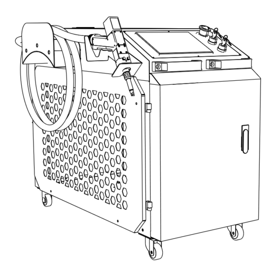
Page 30: Weld Unit Front View
Laser output fiber Infrared radiation is delivered to the welding torch through this fiber. Optical fibers are transmitted through umbilical cable. AC input socket:230V~,50/60Hz,40A (LWH 1500) AC line input 230V~,50/60Hz,45A (LWH 2000) Operating Instruction... -
Page 31: Laser Welding Torch
Laser Welder Device Description 3.4 Laser welding torch Item Function Description Press and hold Trigger 1 to begin shielding gas ow. This must Trigger 1 - remain pressed throughout the welding process. Trigger 1 should Start Gas Flow only be released once Trigger 2 is no longer being pressed Under safety conditions,trigger 2 functions:... -
Page 32: Layout And Dimensions(Cm)
Laser Welder Device Description 3.5 Layout and dimensions(cm) 3.6 Fiber cable output connection The input voltage to the laser can be lethal. All fibers and connections should be considered at hazardous levels. All parts of fiber optics, connectors, or device enclosures should be considered hazards. -
Page 33: 四、Conditions Of Use
Use of chiller 4 Conditions of use 4.1.1 Environmental requirements ◆ Ambient temperature: 0 ~ 45℃; ◆ Relative humidity: ≤90%; ◆ Altitude: ≤3000m; ◆ The relationship between the temperature of the cooling medium and the ambient temperature is shown in Figure 2. Normal operating range Ambient temperature℃... -
Page 34: Medium Requirements
Use of chiller 4.1.2 Medium requirements The cooling medium must be softened water, such as pure water, distilled water, high pure water, etc., the volume ratio ≤30% ethylene glycol, or the volume ratio ≤20% ethanol, and the preservatives and bacteria removers approved by the manufacturer are allowed to be added. It is strictly prohibited to use antifreeze with the volume ratio of >... -
Page 35: Exhaust And Drainage
Use of chiller 4.2.2 Exhaust and drainage After the first addition of water and replacement of new water, exhaust the air in the pump to start the use, otherwise it will damage the equipment. Exhaust method: slowly loosen the air-exhaust screw plug of the pump (do not screw off), discharge air until water flows out, and then tighten the air-exhaust screw plug (see Figure 4, in which only the exhaust positions of vertical pump and horizontal pump are shown. -
Page 36: Controller Panel Introduction
Use of chiller 4.3.2 Controller Panel Introduction Figure 5 Split controller panel Digital tube Display measuring temperature (low temperature water L.xx.x/normal-tem- perature water H.xx.x) ,setting temperature display (low temperature water Display window S.xx.x/normal-temperature water difference d.xx.x) ,alarm code (Exx), parameter code (Fxx). Indicator light Light up: unit operation;... -
Page 37: Controller Temperature Display
Use of chiller 4.3.4 Controller Temperature Display By default, the display window displays the temperature of the low temperature water measurement (L.xx.x). When the temperature is displayed, press the <▼> key to carry out the display switching of the normal temperature water measurement temperature(H.xx.x), the low temperature water setting temperature (S.xx.x), the normal temperature water setting temperature difference (d.xx.x).30 s no switching operation automatically returns to the low temperature water interface. -
Page 38: Maintenance
Maintenance 4.5 Maintenance The machine must be stopped and the power must be cut off for 3 minutes before equipment mainte- nance, otherwise there will be electric shock risk. When the ambient temperature is lower than 2℃, the internal water must be drained when the machine stops for a long time. 4.5.1 Dustproof in summer In summer, please clean the condenser and dust screen of the equipment in about 15 days, as shown in Figure 6. - Page 39 Maintenance When the equipment is transported or not in use for a long time, the water in the water tank shall be drained through the sewage valve, and the drain screw under the pump shall be unscrewed to plug and drain away the remaining water in the pump, as shown in Figure 12.
-
Page 40: Routine Maintenance
Maintenance 4.6 Routine maintenance The working scene of the Fiber Laser Chiller is very bad. In order to ensure the good performance of the equipment and extend its service life, the equipment needs to be maintained once a week. The mainte- nance work includes but is not limited to the following aspects. -
Page 41: Circuit Diagram
Circuit diagram 4.7 Circuit diagram Pump Compressor fan Low temperature probe Normal temperature probe FIG. 9 Circuit diagram of 220V equipment Operating Instruction... -
Page 42: 五、Installation Of Welding Equipment
Installation Of Welding Equipment 5. Installation Of Welding Equipment 5.1 Precautions Refer to Specifications for correct power requirements. Before applying power, ensure that the input voltage is equal to the level stated in the specifica- tions.Operate only in an environment with sufficient air circulation that allows the specified heat load to occur during operation. -
Page 43: Airflow And Mounting Clearance
Installation Of Welding Equipment 5.2 Airflow and Mounting Clearance The laser welder unit is cooled by liquid circulation. When placing the laser welding machine, leave a gap of about 20cm on the left and right and the rear of the welding machine to facilitate the convection heat dissipation of the radiator. -
Page 44: Connect The Power Supply
Installation Of Welding Equipment 5.4 Connect the power supply For power requirements, please refer to the product specification of the laser welder. Feature Speci cation Single-phase input AC 230V~ 230V~ full load current Enter the AC frequency 50/60 Hz 50/60 Hz Connect the power input to the indicated voltage, phase and frequency. -
Page 45: System Startup
Installation Of Welding Equipment 5.6 system startup Before powering the unit, all electrical connections must be checked and the tank water level confirmed. If applicable, all connections must be secured to ensure proper function. When handling this product, be sure to wear appropriate personal protective equipment. These include welding masks, gloves and laser safety glasses suitable for use at the 1080nm wavelength. - Page 46 LCD Panel 6. LCD Panel The control system of LWH2K consists of touch screen and controller. The touch operation interface has 5 pages of welding, process, expert library, wire feeding and setting. The specific use and parameter description are as follows. 1)...
- Page 47 LCD Panel 2)Parameters 【Parameter】is the interface for adjusting and modifying welding parameters. By entering the process package number in the process name, the process parameters corresponding to the name can be called up; after adjusting the process, you need to click the save button, and the process parameters will be automatically saved to the internal memory, after switching to the [Welding] page, the modified process will be called automatically.
- Page 48 LCD Panel 3)Expert presets 【Expert presets】stores welding process parameters of different materials and plate thicknesses, which are stored in the default storage area. This parameter can effectively improve the debugging efficiency. This parameter needs to be exported and saved in the selected process package before it can be used or modified.
- Page 49 LCD Panel One-Button Wire Feeding—specified length of wire feeding after pressing Stop - the wire feeder stops when pressed L-- Press To Switch L/M/H to adjust the wire feeding speed Wire Feeding Setting--press to enter the wire feeding interface 5) Wire Settings The parameters in the【Settings】page are global variables related to welding.
- Page 50 LCD Panel Settings 6) The parameters in the【Settings】page are global variables related to welding. By changing the parame- ters of this page, the changes and applications of the variables in the entire system can be realized. Parameter Description: Laser nominal power (W)—The rated power of the laser generator Pulse welding time (ms)—The time from when the light is triggered to the light is automatically turned o (the light is emitted again, and the light needs to be manually triggered again) Wire feeding compensation (ms)—The wire feeding time compensate Laser center (mm) - laser center point...
-
Page 51: 六、Lcd Panel
Operate Laser Welding Machine 7. Operate Laser Welding Machine 7.1 Important Safety Functions 7.1.1 Fiber optic connection The connection between the laser QBH connector and the manual welding head provides a normally closed signal output. If the fiber connected to the welding head is unplugged or disconnected, the internal laser will turn off the light. -
Page 52: Welding Torch Two-Stage Triggers
Operate Laser Welding Machine 7.2 Nozzles and Nozzle Tubes on welding torch 7.2.1 Nozzle types 3 types of nozzles for choice Standard nozzle with one point 7.2.2 Nozzle installation Before replacing the nozzle, use the key switch to turn off the unit. The nozzle will pass through the extension tube of the welding head. -
Page 53: Adjust The Nozzle Tube
Operate Laser Welding Machine 7.2.3 Adjust the nozzle tube Use the key switch to turn off the unit before adjusting the extension tube. 1. To adjust the extension tube, first loosen the nut as shown on the left 2. Once the extension tube is properly positioned, tighten the nut to lock the nozzle tube in place as shown on the right. - Page 54 Maintenance 8. Maintenance The input voltage of the laser welding unit can be lethal. All fibers and connections should be considered at hazardous levels. All parts of fiber optics, connectors, or device enclosures should be considered hazardous. The device is classified as a high power Class IV laser instrument. This product emits invisible radiation with a wavelength of 1080nm.
- Page 55 Maintenance 8.4 Disconnect fiber output The welder should be switched off and the AC power connection unplugged before any maintenance is performed on the weld head. Care should be taken when disassembling and assembling the QBH connector to avoid damage to the quartz block and to ensure that the surface of the quartz block is clean.
- Page 56 Maintenance 8.5 QBH Quartz Block Cleaning Procedure Every time the fiber output connected to the welding head is disconnected, the fiber QBH quartz block end face must be checked for dust , dirt or damage, it is recommended to clean according to the following items: ・...
- Page 57 Maintenance Wipe the surface horizontally Do not let the area where your fingers touch the lens tissue touch the surface being cleaned. 1. Recheck the surface 2. If the acetone is still contaminated, repeat step 7. 3. If necessary, you should place a drop of acetone on the cleaning swab and use a circular motion to remove contamination, never scratching the surface.
-
Page 58: 八、Maintenance
Common Abnormity Handling 9. Common Abnormity Handling 9.1 The screen does not light up/click does not respond The screen does not light up, if the controller is powered on (the fan is running), check whether the four-core wire between the controller and the screen is connected correctly. 9.2 No light The monitoring interface can exclude other alarms. - Page 59 Service and Support 10. Service and Support When the customer uses parts that are not serviceable in the field, please consult the after-sales personnel for maintenance matters. Questions about the safety, setup, operation, and maintenance of the product can be resolved by reading this user guide carefully. If you have any questions about the safety, setup, operation or maintenance of the product, please contact customer after-sales personnel.
- Page 60 Wechat ID TRM Technology, Inc. For inquiries regarding the content of this document, please get in touch with our sales department. Add: #9, Huanbaosanlu, Xinbei District, Changzhou,Jiangsu 213034,China. Version No. :V1.1 Tel: 0519-85777780 85866920 Revision Date:2023-04-04 Fax: 0519-85777786 Email:sales@termmei.com...
Need help?
Do you have a question about the LWH 1500 and is the answer not in the manual?
Questions and answers