
Related Manuals for Arbiter Systems 1073A

Summary of Contents for Arbiter Systems 1073A
- Page 1 MODEL 1073A DISTRIBUTION AMPLIFIER OPERATION MANUAL 1073A DISTRIBUTION AMPLIFIER OPERATE ARBITER SYSTEMS, INC. PASO ROBLES, CALIFORNIA U.S.A.
- Page 2 This manual is issued for reference only, at the convenience of Arbiter Systems. Every reasonable effort was made to verify that all contents were accurate as of the time of publication. Check with Arbiter Systems at the address below for any revisions made since the original date of publication.
- Page 3 LIMITED WARRANTY Arbiter Systems makes no warranty, expressed or implied, on any product manufactured or sold by Arbiter Systems except for the following limited warranty against defects in materials and workmanship on products manufactured by Arbiter Systems. Products manufactured by Arbiter Systems are guaranteed against defective materials and workmanship under normal use and service for one year from date of delivery.
- Page 5 • Table of Contents • Section One: General Information • Section Two: Technical Specifications & Operational Parameters • Section Three: Physical Configuration • Section Four: Operation © Copyright Arbiter Systems Incorporated Jan. 2003 All rights reserved. International copyright secured. PD0022300A...
-
Page 7: Table Of Contents
Table of Contents General Information ........................1 1.1 Scope............................. 1 1.2 Equipment Supplied......................1 1.3 Options..........................1 1.3.1 Option 01, Fiber Optic Input for Channel A: ..............2 1.3.2 Option 04, ON/OFF Switch: ..................2 1.3.3 Option 07, IEC-320 Power Inlet, 85-264Vac, 110-275Vdc:......... 2 1.3.4 Option 08, 10-85Vdc Terminal Power Strip, Surge Withstand: ........ -
Page 9: General Information
Self-Adhesive Rubber Feet (P/N: HP0006600): For bench-top applications, four self-adhesive rubber feet are included. 1.3 Options. The Model 1073A allows for installation of options, which can enhance various aspects of performance and/or features. The following is a list of available options:... -
Page 10: Option 01, Fiber Optic Input For Channel A
Section 1: General Information 1.3.1 Option 01, Fiber Optic Input for Channel A: Provides a fiber-optic input (channel A only) with ST connector and 820 nm receiver compatible with multi-mode fiber (50/125 or 62.5/125 µm). Accepts -25.4 to -9.2 dBm for +5V logic level and <-40 dBm for 0 V logic level for dc to 5 MHz. -
Page 11: Technical Specifications And Operational Parameters
2.1 2.1 Scope. This section contains information pertinent to the functional and operational characteristics of the the Model 1073A Distribution Amplifier. Topics presented in this section are: Operator Interface(s), System Interface(s) and Physical Characteristics. NOTE: Specifications are subject to change without notice. -
Page 12: Physical Characteristics
Section 2: Technical Specifications Output Connectors: Four 50-ohm BNC per channel Driver Each output, 74HC125 quad buffer; all four gates paralleled AC coupled Level 5 Vpp, open-circuit, 2.5 Vpp (+12 dBm) into 50 ohms 50 ohms + 0.1 µf capacitor, nominal Impedance DC coupled Level 5 Vpp, open circuit... -
Page 13: Physical Configuration
3.1.2 Power Requirements. The standard AC input voltage range for the Model 1073A Distribution Amplifier is either 85Vac to 264Vac, 47 Hz to 440 Hz., 110 to 275Vdc; or 10 to 85Vdc. See Section 3.1.3. 3.1.3 Power Line Connection. - Page 14 Section 3: Physical Configuration 3.1.3.1.2 DC operation. For 110-270 Vdc operation, the dc voltage should be applied between the LINE and NEUTRAL terminals of the power inlet module, without regard to polarity (the internal power supply will accept either polarity). When viewing the power inlet module from the rear of the instrument, the LINE connection is the one nearest the bottom, and the NEUTRAL is nearest the top.
-
Page 15: Rear Panel Layout
(Option 08) 5 x 20 mm fuse. No spare fuse is provided for Options 08 or 10. 3.1.4 Rear Panel Layout. When viewed from behind, the rear panel of the Model 1073A is arranged in the following manner, left to right (see Figure 3-1): •... -
Page 16: Rack Mounting
Section 3: Physical Configuration 3.2 Rack Mounting. Rack mounting ears are included with the 1073A, to facilitate mounting the instrument in a standard 483 mm (19 inch) equipment rack. To install the rack mounting ears, observe the following steps: 1. Using a T-25 driver, remove the two screws on one side of the unit. Leave the cover in place. -
Page 17: Input Characteristics
Section 3.4.5. 3.4.2 Input Characteristics. In ac-coupled mode, the approximate input impedance of the Model 1073A is 100 ohms, and the input is transformer isolated. AC-coupled inputs may be driven with sine or square waves having levels of 0 to +15 dBm, or 200 mVrms to 1.2 Vrms from a 50-ohm source. For a low-impedance source, recommended levels are 600 mVpp to 5 Vpp. -
Page 18: Output Characteristics
Section 3: Physical Configuration corresponding output connector; however, each jumper is located adjacent to the respective output connector. Table 3-1. Output Jumper List Channel Jumper Connector JMP3 JMP4 JMP5 JMP6 JMP10 JMP11 JMP12 JMP13 JMP17 JMP18 JMP19 JMP20 3.4.4 Output Characteristics. Four drivers of a 74HC125-bus buffer in parallel drive each output. -
Page 19: Input Bussing
'B' position. The position of JMP14 has no effect on operation. 3.5 Fiber Optic Input (Option 01). When Option 01 is installed, the Model 1073A also has a fiber-optic receiver which is connected in parallel with channel-A input, dc-coupled optocoupler's output. To use the fiber-optic receiver, connect an optical signal meeting the requirements listed in section 3.5.1, and follow the... -
Page 21: Operation
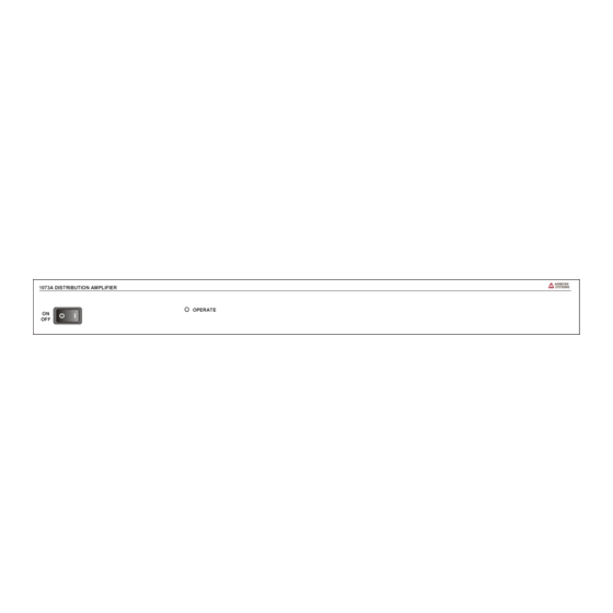
OPERATE Figure 4-1. Model 1073A Distribution Amplifier Front Panel 4.1.1 LED Status Indicators The Model 1073A is provided with a single LED, which illuminates when power is applied to the Model 1073A. 4.1.2 Front Panel Line Switch (Option 04). When Option 04 is installed, the Model 1073A is provided with a front-panel line switch. When this option is not installed, a hole plug is mounted in this location.
Need help?
Do you have a question about the 1073A and is the answer not in the manual?
Questions and answers