Table of Contents
Advertisement
Quick Links
Advertisement
Table of Contents

Subscribe to Our Youtube Channel
Related Manuals for QTS AN-X3-GENI

Summary of Contents for QTS AN-X3-GENI
- Page 1 AN-X3-GENI User Manual Genius I/O Communication Module...
- Page 2 Page AN-X3-GENI January 2024 Because of the variety of uses for the products described in this publication, those responsible for the application and use of these products must satisfy themselves that all necessary steps have been taken to assure that each application and use meets all performance and safety requirements, including any applicable laws, regulations, codes and standards.
-
Page 4: Table Of Contents
MODULE OVERVIEW Hardware Features Package Contents Using the microSD Card AN-X3 Modes of Operation INSTALLATION Prevent Electrostatic Discharge Power Genius Cabling and Termination Ethernet Cabling CE Installations QUICK START IP ADDRESS CONFIGURATION Initial IP Configuration Prosoft Discovery Service Link-Local IP Configuration microSD Config.txt Web Page IP Configuration DHCP... - Page 5 AN-X3-GENI Page Setting the Bus Address and Baud Rate Configuring Genius I/O and Ethernet/IP Scheduled Data Manual Configuration Configuration Sample Files Sample I/O Configuration File Sample Ethernet/IP Configuration File Viewing and Retrieving the Current Configuration Genius Configuration File Format Ethernet/IP Configuration File Format...
- Page 6 Page AN-X3-GENI January 2024 Log Files Genius I/O Fault Log Ethernet AB/CSP Log Ethernet/IP Log System Info Log View All Logs Administration Menu AN-X IP/FW Configuration AN-X Firmware Update Diagnostic Capture AN-X Module Restart Support Menu TROUBLESHOOTING LEDs Ethernet LEDs...
-
Page 7: Module Overview
Module Overview The AN-X3-GENI allows an Ethernet/IP Client such as ControlLogix to control Genius I/O and exchange data on a GE Genius network. The module supports scheduled connections with a ControlLogix processor, over Ethernet, so the ControlLogix processor can read inputs from the Genius network and write outputs. -
Page 8: Hardware Features
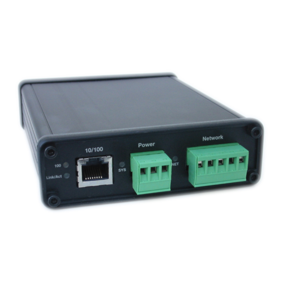
LED to indicate the state of communications on the Genius network (NET) • an Ethernet connector • a Genius network connector • a power connector Package Contents • AN-X3-GENI module • 3 pin Phoenix power connector • 5 pin Phoenix Genius network connector Current firmware and documentation are at qtsusa.com/dist... -
Page 9: Using The Microsd Card
AN-X3-GENI Page Using the microSD Card The AN-X3 microSD card stores configuration data and firmware. The are no restrictions on the size or speed of the card. The format must be FAT-16 or FAT-32. The card must be present while the AN-X3 is running. -
Page 10: Installation
Page AN-X3-GENI January 2024 Installation Prevent Electrostatic Discharge The module is sensitive to electrostatic discharge. Electrostatic discharge can damage integrated circuits or semiconductors. Follow these guidelines when you handle the module: • Touch a grounded object to discharge static potential WARNING! •... -
Page 11: Genius Cabling And Termination
Ensure that the physical ends of the Genius I/O network are properly terminated. The AN-X module does not have any internal termination. Set the baud rate and serial bus address for the AN-X3-GENI module WARNING! before connecting it to the Genius network so the module does not interfere with the existing nodes on the Genius network. -
Page 12: Ce Installations
Page AN-X3-GENI January 2024 CE Installations If you are installing the AN-X3 in a location which requires CE, install the following ferrites or their equivalents on the cables: Steward 28A3851-0A2 two passes on serial cable 2 Steward 28A2025-0A0 on Ethernet cable... -
Page 13: Quick Start
Genius devices and perform any other necessary configuration. Use the AN-X web interface to set the baud rate and serial bus address for the AN-X3-GENI Connect AN-X to the Genius network Use the AN-X web interface to autoconfigure the Genius... -
Page 14: Ip Address Configuration
Page AN-X3-GENI January 2024 IP Address Configuration Before you can use the AN-X3-GENI, you must configure its IP address on Ethernet. For the options and best procedures to configure AN-X3 modules, see: https://qtsusa.com/dist/AN-X3/AN-X3_ReadMe_and_QuickStart.txt Initial IP Configuration AN-X can be configured: ... -
Page 15: Prosoft Discovery Service
AN-X3-GENI Page Prosoft Discovery Service Prosoft Discovery Service (PDS) is a free Windows aplication available from Prosoft’s web page: https://www.prosoft-technology.com/Products/ProSoft-Software/ProSoft-Discovery-Service With the AN-X3 module connected to Ethernet and powered up, run PDS. It should find any AN-X modules on the network. -
Page 16: Link-Local Ip Configuration
Page AN-X3-GENI January 2024 Link-Local IP Configuration ** Many computers do not allow access to link-local addresses by default. If you are using link-local IP addresses to configure multiple AN-X3 modules, connect and configure one at a time, since initially they will all be set to the same link-local IP address. - Page 17 AN-X3-GENI Page If you edit the file and AN-X3 finds an error during startup, it flashes an error code on the SYS (or MS) LED, see page 58. Example config.txt files Example: DHCP IP: DHCP Hostname: AnxGeni Firmware: AN-X3-GENI-MAS Example: static IP address IP: 10.10.2.141...
-
Page 18: Web Page Ip Configuration
Page AN-X3-GENI January 2024 Web Page IP Configuration Select Administration/AN-X Configuration. The AN-X Configuration page appears. The serial number and MAC address of the AN-X being configured are shown. Check either DHCP or Static. If Static, fill in the required fields. -
Page 19: Hostname
Select the firmware the AN-X is to load from the list provided. AN-X builds the list from the firmware files on the microSD card that are compatible with the AN-X hardware. The firmware file for Genius operation is AN-X3-GENI-MAS.v4.x.x.qtf Submitting the Configuration Once you have entered all required parameters, click SUBMIT to write the configuration to the file config.txt on the microSD card. -
Page 20: Reconfiguring An An-X From An Unknown State
If the AN-X3 microSD becomes corrupted and the AN-X3 will no longer boot, or if you want to reinitialize the AN-X3 to factory state: Download the appropriate factory image file from the QTS web site. qtsusa.com/dist/AN-X3 (AN-X3-GENI-uSD.v4.01.01.img.zip for example). WARNING: This process will erase all AN-X3 configuration files. -
Page 21: Genius Network Configuration
Enter the serial bus address (SBA) for the AN-X, in the range 0 to 31. This must be a free node number on the existing Genius Network. Click the Submit Changes button to set the Genius bus properties of the AN-X3-GENI. -
Page 22: Configuring Genius I/O And Ethernet/Ip Scheduled Data
Page AN-X3-GENI January 2024 Configuring Genius I/O and Ethernet/IP Scheduled Data The AN-X-GENI uses two text files for configuration. The I/O configuration text file defines the Genius I/O Blocks and Devices the AN-X will scan. The Ethernet/IP configuration file defines data mapping between the Ethernet/IP Scheduled Owner and the I/O Blocks and Devices. -
Page 23: Manual Configuration
Configuration Sample Files Sample I/O and Ethernet/IP configuration files are available by selecting Automation Network/Configuration Sample. Sample I/O Configuration File ;QTS AN-X-GENI Scan Configuration Utility ;Copyright (c) 2005 Quest Technical Solutions ;Auto Config Geni I/O File Block=1,Inp=32,Out=2,Scan,Part="IC660BBD120",Desc="High-speed Counter Block",EndBlock Block=2,Inp=2,Out=2,Scan,Part="IC660BBR101",Desc="16-Ckt Normally-open Relay Block",EndBlock Block=3,Inp=4,Out=4,Scan,Part="IC660BBD024",Desc="12/24VDC 32 Ckt Source I/O Block",EndBlock... -
Page 24: Sample Ethernet/Ip Configuration File
Page AN-X3-GENI January 2024 Sample Ethernet/IP Configuration File ;QTS AN-X-GENI Scan Configuration Utility ;Copyright (c) 2005 Quest Technical Solutions ;Auto Config Ethernet/IP File (AutoScan Ver 4.1.6) ;ScanGeniProg LedModeDebug ClxName,AnxGeniMas ClxPrefix,GENI_ ClxSlot,0 DataOutput ; Outputs from ControlLogix ,b1,b01_Out, ; Ofs= 0 Len= 1 IC660BBD120 High-speed Counter Block ,b2,b02_Out, ;... -
Page 25: Viewing And Retrieving The Current Configuration
AN-X3-GENI Page ;,m31>5[2],b05_OutMon, ; Ofs= 7 Len= 2 IC660BBA020 24/48VDC 4In/2Out Analog Block ;,m31>10[12],b10_OutMon, ; Ofs= 9 Len=12 IC670GBI001 Field Control Genius Bus Interface Unit ;,m31>11[2],b11_OutMon, ; Ofs= 21 Len= 2 IC200GBI001 VersaMax Genius Network Interface Unit ;The following lines map Diagnostics into ClxSlot 15... - Page 26 0. If the AN-X3-GENI is to control the outputs on a module, include the keyword Scan. If the AN- X3-GENI is only to monitor the inputs on a module, omit the keyword Scan.
-
Page 27: Ethernet/Ip Configuration File Format
Ethernet/IP Configuration File Format The AN-X3-GENI supports scheduled connections with a ControlLogix processor over Ethernet. The AN-X3-GENI behaves like a 17-slot ControlLogix rack with an ENBT/A module in slot 16 and generic modules in slots 0 to 15. A ControlLogix processor can open a scheduled connection to each of these 16 generic modules. - Page 28 For example, if the ControlLogix has connections to two AN-X3-GENI modules, each controlling a different Genius network, each Genius network could have a block with the same serial bus address. Using a different ClxPrefix in the configuration file for each AN-X3-GENI makes the aliases for the two AN-X modules distinct.
-
Page 29: Global Data
AN-X3-GENI Page Data definitions consist of lines that define the mapping between the ControlLogix data table and the Genius module. They consist of lines of the form CLX_offset (optional), Genius_Node, tagname The CLX_offset is the offset into the data for the connection. You can select the offset where the data is located or you can leave it blank and AN-X will automatically assign the offset. - Page 30 Receiving Global Data on the AN-X3-GENI When you perform an autoconfiguration, if the other node is producing global data when you autoconfigure the AN-X3-GENI, the autoconfiguration will include the global data. If you are configuring the Genius network manually, add a line of the form Block=nn,Inp=inlength,Out=0,,Part="partnumber",Desc="description",EndBlock...
-
Page 31: Other Mappable Data
The ControlLogix processor that is the exclusive owner of the connection to the generic module in slot 0 controls how the AN-X3-GENI module scans the Genius network. For that reason, when you map the data, you must always include a connection to the generic module in slot 0. -
Page 32: Diagnostic Counters
Page AN-X3-GENI January 2024 Diagnostic Counters The AN-X3-GENI maintains the following diagnostic counters. Counter Offset Description TxFrames Transmitted network frames TxMsgs Transmitted network messages (datagrams) RxFrames Received network frames RxMsgs Received network messages (datagrams) RxDup Received duplicate frames RxCrcErr Received frames with a CRC error... -
Page 33: Block Fault Table
Example: ,BlockFlt If the block fault bit is set for a block, use the web interface on the AN-X3-GENI to view and clear the fault. Refer to page 50 for details. Connection Diagnostics The AN-X3-GENI maintains diagnostics related to the UDP traffic to and from the module. -
Page 34: Connection 15 Mappings
Page AN-X3-GENI January 2024 The statistics for each connection consists of 10 words of data. Only three words in the ten word block are used. Offset Description Average time for last 32 updates Minimum time since the connection statistics were reset Maximum time since the connection statistics were last reset The units for the times are 0.1 milliseconds. -
Page 35: Configuring The An-X Module In Rslogix 5000
AN-X3-GENI Page Configuring the AN-X Module in RSLogix 5000 To configure the AN-X3-GENI in RSLogix 5000: 1. Right click on the ControlLogix Ethernet module that will be communicating to the AN-X and select Add Module. Add a 1756-ENBT/A module. 2. Set the Major Rev to 1. - Page 36 Page AN-X3-GENI January 2024 Set Electronic Keying to Disable Keying. 3. Add Generic modules for each required connection Set the parameters as shown. Set the Slot to 0 for the first connection, 1 for the second connection, and so on.
-
Page 37: Controllogix Aliases
AN-X3-GENI Page ControlLogix Aliases AN-X uses the Ethernet/IP configuration to create aliases that can be imported into RSLogix 5000. Use these alias tags in your RSLogix 5000 program to access the data on the AN-X. There are two sets of alias files, one for exclusive owner connections and one for listen only connections. -
Page 38: Using The Ethernet/Ip Log
ControlLogix via scheduled connections. Ghost mode is useful when the AN-X3-GENI and a ControlLogix is to replace an existing control system and you want to verify the data and timing on the existing system before replacing it. - Page 39 AN-X3-GENI Page The CLX_offset is the offset into the data for the connection. You can select the offset where the data is located or you can leave it blank and AN-X will automatically assign the offset. The Genius_location consists of an address in the form msourceSBA>destSBA[length]...
- Page 40 4. Save and edit the Genius configuration file. Remove Scan from all network devices. 5. Save and download the modified Genius configuration file to the AN-X3-GENI. 6. Save and edit the ControlLogix confguration file the AN-X3-GENI created when you performed the autoconfiguration. Comment out all the DataOutput sections.
-
Page 41: Ethernet Plc-5 File Emulation
The AN-X3-GENI supports Word Range read/write, Typed read/write, Read/Modify/Write, and PLC-3 Bit Write messages, with both logical ASCII and logical binary addressing. To configure a topic in RSLinx to access data on the AN-X3-GENI: 1. Create a new topic. From the main menu select DDE/OPC/Topic Configuration. Click New and give the topic a name. -
Page 42: Using Rslinx To View Data
Page AN-X3-GENI January 2024 Using RSLinx to View Data AN-X3 appears to RSLinx to be an Ethernet PLC-5, specifically a PLC-5/20E. First create an Ethernet driver to communicate with the AN-X3. If you right click on the AN-X3 module in RSLinx and select Data Monitor, a list of files... - Page 43 AN-X3-GENI Page Each file corresponds to the data for one DCS drop. File N100 corresponds to drop 0, N101 corresponds to drop 1 and so on. To view the drop data, double click on the appropriate file. To change the display format, right click on the data display and select Properties, then select the...
-
Page 44: Accessing Global Data From Hmis
5, and read the data from the appropriate integer file. You can also use an HMI to write to the global data that the AN-X3-GENI is transmitting, that is, the file that corresponds to the AN-X3-GENI serial bus address. Of course, if the AN-X3-GENI global data is mapped to a ControlLogix connection, the global data you write using the HMI will be overwritten by the data from the scheduled data. -
Page 45: Using The Web Interface
The AN-X module contains a webserver capable of communicating with standard web browsers such as Chrome or Firefox. Use the web interface to: set the baud rate and serial bus address for the AN-X3-GENI set the Genius bus I/O network configuration ... - Page 46 Page AN-X3-GENI January 2024 The contents of the right pane depend on the current command being executed. Browsers may return cached data rather than rereading data that has changed on the AN-X. Run the browser in a mode where it doesn't cache data (incognito in Chrome, Private browsing in Firefox and Safari, etc.)
-
Page 47: Automation Network
AN-X3-GENI Page Automation Network The Automation Network Configuration functions are described previously in this document. Monitor Genius Network Select Automation Network/Monitor Genius Network to display I/O scanner status, diagnostic counters and I/O data. Checkboxes may be used to choose which nodes to display. -
Page 48: Monitor Ethernet/Ip
Page AN-X3-GENI January 2024 Monitor Ethernet/IP Select Automation Network/Monitor Ethernet/IP to display Ethernet/IP status and diagnostic counters. Ethernet/IP UDP Statistics The Ethernet/IP Statistics consist of two portions: Global counters Statistics for each connection The Global Counters consist of:... - Page 49 AN-X3-GENI Page The Connection Statistics consist of: Counter Description Connection number 0 to 15 Status Active or Idle Rx Tout The receive timeout, calculated from the RPI Rx Avg The average of the last 32 update times, in ms. Rx Min The minimum update time since the last counter reset, in ms.
-
Page 50: Log Files
Page AN-X3-GENI January 2024 Log Files AN-X maintains various logs to record diagnostic and error messages. Use the Log Files menu in the web interface to view these logs. Genius I/O Fault Log Genius bus modules can return fault information. If a module that is being controlled by the AN-X-GENI returns a fault, you can use the web interface to view and clear the fault. -
Page 51: Ethernet/Ip Log
AN-X3-GENI Page Ethernet AB/CSP Log The AN-X module maps Genius nodes 0 to 31 to PLC-5 files N100 to N131. The Ethernet AB/CSP log shows messages and errors associated with this PLC-5 Emulation. Ethernet/IP Log The Ethernet/IP log shows messages and errors associated with the Ethernet/IP communication, both scheduled and unscheduled. -
Page 52: An-X Firmware Update
Page AN-X3-GENI January 2024 AN-X Firmware Update Use AN-X Firmware Update to transfer a firmware file to the microSD card on the AN-X. Firmware files for the AN-X3 have names that begin with AN-X3 and have extension *.qtf. Do not update firmware in the AN-X while applications that use the WARNING! AN-X are running. - Page 53 AN-X3-GENI Page AN-X displays progress and status information as the firmware is updated.
-
Page 54: Diagnostic Capture
Page AN-X3-GENI January 2024 When the update is complete, AN-X displays a message that indicates the success or failure of the update. If you have other files to transfer, return to the main page and continue. Otherwise, restart the AN-X in order to run the updated firmware. -
Page 55: An-X Module Restart
AN-X3-GENI Page AN-X Module Restart Use the AN-X Module Restart command to restart the AN-X module, for example, after changing Ethernet parameters or after updating firmware. Support Menu The Support menu contains Contact Information. -
Page 56: Troubleshooting
January 2024 Troubleshooting LEDs The AN-X3-GENI has LEDs that indicate the state of the Ethernet connection, the overall module state and the connection to the Genius I/O network. Ethernet LEDs There are two LEDs that indicate the state of the Ethernet connection. -
Page 57: Ms And Ns Leds: Runtime
AN-X3-GENI Page It railroads the LEDs yellow while it is copying new maintenance or production firmware files from the microSD card to flash memory. It railroads the LEDs green for 20 to 30 seconds as it starts production mode. MS and NS LEDs: Runtime There are two possible runtime LED modes. -
Page 58: Fatal Errors
Page AN-X3-GENI January 2024 Debug Mode SYS or MS LED The SYS or MS LED is used by the AN-X operating system and software to indicate the state of operations and errors. The SYS or MS LED should be used in conjunction with the logs to locate the cause of problems. -
Page 59: Updating The Firmware
AN-X to use. Obtaining the Latest Software Version numbers and software for the most recent AN-X3 releases are available from the QTS website, qtsusa.com/dist... -
Page 60: Specifications
Page AN-X3-GENI January 2024 Specifications Parameter Specification Function Bridge between Ethernet and Genius network Typical Power Consumption 200 mA @ 12 VDC or 100 mA @ 24 VDC Maximum Power dissipation 2.4W Environmental Conditions: Operational Temperature 0-50°C (32-122°F) Storage Temperature –40 to 85°C (–40 to 185°F) -
Page 61: Support
AN-X3-GENI Page Support How to Contact Us: Sales and Support Sales and Technical Support for this product are provided by ProSoft Technology. Contact our worldwide Sales or Technical Support teams directly by phone or email: Asia Pacific Languages Spoken: Chinese, English +603.7724.2080,... -
Page 62: Warranty
Page AN-X3-GENI January 2024 Warranty Quest Technical Solutions warrants its products to be free from defects in workmanship or material under normal use and service for three years after date of shipment. Quest Technical Solutions will repair or replace without charge any equipment found to be defective during the warranty period.
Need help?
Do you have a question about the AN-X3-GENI and is the answer not in the manual?
Questions and answers