Advertisement
Quick Links
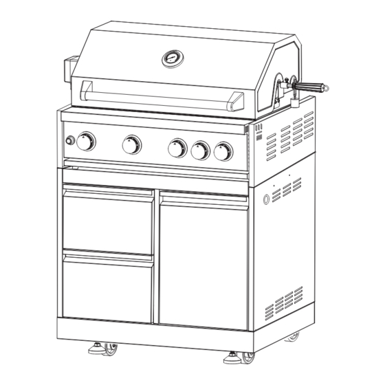
INSTALLATION MANUAL
KoolMore Outdoor Kitchen System
Grill Cabinet Modular
Model:
KM-OKS-BQ30CAB
(Compatible With The KoolMore Outdoor Kitchen System)
For any service-related Issues, please contact
us: Phone Number: 718-576-6342
Email address: support@koolmore.com
Advertisement

Related Manuals for KoolMore KM-OKS-BQ30CAB


Summary of Contents for KoolMore KM-OKS-BQ30CAB
- Page 1 INSTALLATION MANUAL KoolMore Outdoor Kitchen System Grill Cabinet Modular Model: KM-OKS-BQ30CAB (Compatible With The KoolMore Outdoor Kitchen System) For any service-related Issues, please contact us: Phone Number: 718-576-6342 Email address: support@koolmore.com...
-
Page 2: Important Safety Warning
IMPORTANT SAFETY WARNING Adherence to the following instructions is crucial to prevent potential fire, explosion, property damage, personal injury, or even death: • This manual provides important information on the assembly and operation of your appliance. Failure to follow these instructions precisely may lead to hazardous situations. •... - Page 3 GRILL EXPLOSIVE DRAWING...
- Page 4 CABINET EXPLOSIVE DRAWING 71 70 Screw kit...
-
Page 5: Part List
PART LIST Part No. Part Name Quantity Part No. Part Name Quantity Clapboard Welding Part Grill Top Cover Left Side Panel A Welding Assembly Thermometer Beam Welding Assembly Left Handle Holder Tank Bottom Welding Assembly Top Warming Rack Sideway Rotisserie Drawer Assembly Grill Cavity 52.1... - Page 6 CABINET INSTALLATION: STEP 1 1. Flip the Bottom Base Welding Assembly (Part #49) to prepare for the installation of legs and casters. 2. Using 16 pieces of ¼" *14 Philips Thumb Head Screw with Anti-slip Design (Part #71), install 2 Supporting Legs (Part #55), 2 Fixed Casters (Part #56), and 2 Universal Casters with Brake (Part #57).
- Page 7 CABINET INSTALLATION: STEP 2 1. Flip back the Bottom Base after the casters and legs are installed. 2. Use 4 pieces of 5/32" *8 Flat Head Screw (Part # 72) to connect the Tank Bottom Support (Part # 59) to the Bottom Base Welding Assembly (Part # 49).
- Page 8 CABINET INSTALLATION: STEP 3 1. Use 6 pieces of 1/4*14 Philips Thumb Head Screw with Anti-slip Design (Part #71) to connect the Left Side Panel A Welding Assembly (Part #46) and the Right Side Panel A Welding Assembly (Part # 61) to the Bottom Base Welding Assembly (Part #49).
- Page 9 CABINET INSTALLATION: STEP 4 1. Use 3 pieces of 1/4"*14 Philips Thumb Head Screw with Anti-slip Design (Part #71) to install the Back Panel A Welding Assembly (Part # 63) to the Bottom Base Welding Assembly (Part # 49). 2. Use an additional 3 pieces of 1/4*14 Philips Thumb Head Screw with Anti-slip Design (Part #71) to connect the Back Panel A Welding Assembly (Part # 63) with Part # 46 and Part # 61.
- Page 10 CABINET INSTALLATION: STEP 5 1. Use 5 pieces of 1/4*14 Philips Thumb Head Screw with Anti-slip Design (Part #71) to connect the Clap- board Welding Part (Part # 45) with Part #49 and #63.
- Page 11 CABINET INSTALLATION: STEP 6 1. Use 4 pieces of 1/4"*14 Philips Thumb Head Screw with Anti-slip Design (Part #71) to connect the Beam Welding Assembly (Part # 47) with Part #46 and #61.
- Page 12 CABINET INSTALLATION: STEP 7 CABINET INSTALLATION: STEP 6 1. Check the edge of the middle plate of the Drawer Assembly (Part #52) and ensure that the side with the edge is facing up. 2. Use 8 pieces of 5/32" Flat Head Screw (Part # 70) to install the Bottom Plate of the Drawer Assembly (Part# 52.4) to the Middle Plate (Part# 52.3).
- Page 13 CABINET INSTALLATION: STEP 8 CABINET INSTALLATION: STEP 7 1. Insert 2 Drawer Assemblies (Part #52) into the Cabinet Body. 2. Detach the two parts of the Door Hinge (Part #66) and use a 5/32" *8 Flat Head Screw (Part #72) to install them to the Right Side Panel (Part #61) and the Cabinet Door (Part #53).
- Page 14 CABINET INSTALLATION: STEP 9 CABINET INSTALLATION: STEP 8 1. Use 2 pieces of 5/32" *8 Flat Head Screw (Part # 72) to install the Laminate Board (Part #65) to the Left Side Panel A Welding Assembly (Part #46). 2. Use 2 pieces of 5/32" *8 Flat Head Screw (Part # 72) to install the Gas Tank Heat Shield (Part #64) to the Right Side Panel A Welding Assembly (Part #61).
- Page 15 CABINET INSTALLATION: STEP 10 CABINET INSTALLATION: STEP 9 In this first step of installing the outdoor grill, we're going to secure the motor holder, the rotisserie holder, and reinstall the cooking racks. Here' s how to do it: 1. Start by opening the Grill cover. For safety and to avoid any potential damage, remove all three Cooking Racks (Part #29) for the main burners.
- Page 16 GRILL INSTALLATION: STEP 2 GRILL INSTALLATION: STEP 1 The second step involves setting up the rotisserie with the motor. Follow these instructions: 1. Begin by placing the Motor (Part #11) on top of the Motor Support (Part #12). Make sure it sits securely on the support.
- Page 17 GRILL INSTALLATION: STEP 3 GRILL INSTALLATION: STEP 2 The third step involves combining the grill and cabinet components. Follow these instructions: 1. Start by positioning the Grill Body over the Cabinet Body. Make sure that the components align correctly. 2. Secure the Grill Body to the Cabinet Body by using 4 pieces of the 1/4"*14 Philips Thumb Head Screw with Anti-slip Design (Part #71).
- Page 18 KOOLMORE OUTDOOR KITCHEN SYSTEM: CONNECTING CABINETS The Kitchen Outdoor Cabinet can be connected with various other cabinet models. Here are the steps to connect different types of cabinets: Connecting a Corner Cabinet 1. If you have a Corner Cabinet and you want to connect it with another cabinet, use the Corner Cabinet Connecting Plate.
- Page 19 KOOLMORE OUTDOOR KITCHEN SYSTEM: BACK PANELS The Kitchen Outdoor Cabinet can be connected with various other cabinet models. Here are the steps to connect different types of cabinets: Connecting Back Panels 1. If you have two cabinets you want to connect at the back panels, use the Back Cabinet Connecting Plate.
- Page 20 At its sole discretion, Koolmore Supply Inc. may decide to replace the product. In such an event, your replace- ment appliance will carry the warranty for the remaining term of the original unit's warranty period.
Need help?
Do you have a question about the KM-OKS-BQ30CAB and is the answer not in the manual?
Questions and answers