Table of Contents
Advertisement
Quick Links
PFC 2000-4000
Universal Gateway
Instruction Manual
January 18th, 2023 Revision 1
Contents
1. Introduction
2. Setup
3. Wiring
4. Commissioning
5. Field Validating
6. Troubleshooting
7. ProtoNode Information
Appendix
A. PFC Points
B. Address DIP Switch Settings
FPC-N34-0816
BACnet-ProtoNodes
Application
5
The Universal Gateway (ProtoNode) provides monitoring,
remote setpoint, firing rate and burner on/off control to the
6
Energy Management Systems/ Building Automation System/
Building Management System (EMS). It supports the following
12
controllers:
• PFC 2000-4000 with Honeywell Display & Sola Control
18
(4716 software)
28
There are two ProtoNode Options:
30
BACnet ProtoNode: Provides BACnet MS/TP, BACnet/IP, N2,
Modbus TCP communications.
37
LonWorks ProtoNode: Provides Lonworks communication.
39
Intent
45
This document provides the necessary information to facilitate
Gateway installation.
practical, installation and setup detailed information.
intended users are contractors and factory support personnel.
This Instruction Manual includes
FPC-N35-0817
Lonworks-ProtoNodes
The
Advertisement
Table of Contents
Troubleshooting

Summary of Contents for PB PFC 2000-4000
- Page 1 2. Setup Energy Management Systems/ Building Automation System/ Building Management System (EMS). It supports the following 3. Wiring controllers: • PFC 2000-4000 with Honeywell Display & Sola Control 4. Commissioning (4716 software) 5. Field Validating There are two ProtoNode Options: 6.
- Page 2 Revision Notes Rev. 1 Manual created for use with PFC 2000-4000 series Legend Application Appearance PFC 2000-4000 with Honeywell Display & Sola Control 4716 Software. Page 2 of 48 Universal Gateway Instruction Manual...
-
Page 3: Table Of Contents
TABLE OF CONTENTS 1 Introduction ....................5 1.1 BTL Mark – BACnet Testing Laboratory ..................... 5 1.2 LonMark Certification ........................5 2 Setup ....................... 6 2.1 Boiler Setup ............................6 2.1.1 Settings for PFC Boilers with Honeywell Display ................6 2.2 ProtoNode Setup .......................... - Page 4 7 ProtoNode Information .................. 37 7.1 Specifications and Ordering Information .................... 37 7.2 ProtoNode Detailed View ......................... 38 Appendix A. PFC 2000-4000 with Honeywell Control Points List ......39 Appendix B. “A” Bank DIP Switch Settings ............45 Page 4 of 48...
-
Page 5: Introduction
INTRODUCTION Universal Gateway (ProtoNode) is an external, high performance Energy Management System (EMS) multi-protocol gateway that uses the FieldServer ProtoNode Technology. The ProtoNode can support multiple Boilers. It has been pre-programmed to Auto-Discover any Sola Control (4109 or 4716 software) equipped boilers connected to the ProtoNode and automatically configures them for BACnet®... -
Page 6: Setup
SETUP Each ProtoNode has a unique part number located on the underside of the unit. This number should be recorded, as it may be required for technical support. The numbers are as follows: Model Part Number ProtoNode RER - BACnet FPC-N34-0816 ProtoNode LER - Lonworks FPC-N35-0817... -
Page 7: Protonode Setup
ProtoNode Setup A-Bank B-Bank S-Bank Figure 1: ProtoNode showing DIP switch “Banks” on bottom 2.2.1 Select EMS Protocol Set Dipswitches to match Protocol of EMS. Remove ProtoNode cover and check protocol dip switch settings: • The “S0 – S2” bank of DIP switches on the ProtoNode RER BACnet are used to select the various field protocols (BACnet MS/TP). -
Page 8: Enable Auto-Discovery
2.2.2 Enable Auto-Discovery The following table describes “S3” DIP Switch setting for the Enabling Auto-Discovering of known devices attached to the ProtoNode RER or LER. • Power down ProtoNode. • Ensure all boilers are powered and connected to the ProtoNode. •... -
Page 9: Bacnet Ms/Tp Single Node And Multiple Node: Set Mac Address
2.2.3 BACnet MS/TP Single Node and Multiple Node: Set MAC Address • Only 1 MAC address is set for ProtoNode regardless of how many devices are connected to ProtoNode. • Set ProtoNode MAC Address. (Must be between 1 and 127) •... -
Page 10: Bacnet Ms/Tp Single Node And Multiple Node: Set Serial Baud Rate
2.2.4 BACnet MS/TP Single Node and Multiple Node: Set Serial Baud Rate DIP Switches B0 – B3 are used to set the serial baud rate to match the baud rate provided by the Energy Management System. Baud 9600 19200 38400 57600 76800 Figure 3: B0 –... -
Page 11: Bacnet Ms/Tp Single Node: Setting The Device Instance
2.2.6 BACnet MS/TP Single Node: Setting the Device Instance The BACnet single node instance will be set by the “Node Offset” + “MAC Address”. All registers from the devices connected to the ProtoNode will be listed under this single node instance. The registers are organized each devices “Modbus Address.”... -
Page 12: Wiring
WIRING ProtoNode Overview Figure 4: ProtoNode BACnet Page 12 of 48 Universal Gateway Instruction Manual... - Page 13 Figure 5: ProtoNode Lonworks Page 13 of 48 Universal Gateway Instruction Manual...
-
Page 14: Wiring To The Protonode 6 Pin Connector
Wiring to the ProtoNode 6 Pin Connector • The 6 pin connector is the same for ProtoNode BACnet and Lonwork • Pins 1 through 3 are for Modbus RS-485 devices. The RS-485 GND (Pin 3) is not typically connected. • Pins 4 through 6 are for power. -
Page 15: Pfc 2000 - 4000 With Honeywell Control: Network Wiring
PFC 2000 – 4000 with Honeywell Control: Network Wiring IMPORTANT NOTES: • PFC 2000-4000 with Honeywell Controls are able to do both Lead Lag (Sequencer) and EMS communication at the same time. Page 15 of 48 Universal Gateway Instruction Manual... -
Page 16: Protonode Bacnet Wiring
ProtoNode BACnet Wiring Wiring the BACnet ProtoNode to the Network (RS-485 Field Protocol) • Connection from ProtoNode RER to BACnet MS/TP, and Metasys N2 network. • See Section 4.2 for information on connecting the BACnet ProtoNode to a BACnet IP network. •... -
Page 17: Protonode Lonworks Wiring
ProtoNode LonWorks Wiring • Connect the ProtoNode to the field network with the LonWorks terminal using a twisted pair non- shielded cable. LonWorks has no polarity. ProtoNobe IP Wiring • Connect the ProtoNobe to the field IP Network at the Ethernet Port using a standard CAT5 Ethernet Cable. -
Page 18: Commissioning
COMMISSIONING 4.1 Use the ProtoNode Web Configurator to setup the Gateway First, connect a standard CAT5 Ethernet cable (straight through or cross-over) between the local PC and ProtoNode. There are two methods to access the ProtoNode via Ethernet connection, either by changing the subnet of the connected PC (Section 4.1.1) or using the FieldServer Toolbox to change the IP Address of the ProtoNode (Section 4.1.2). -
Page 19: Changing The Ip Address Of The Protonode With Fieldserver Toolbox
Highlight > • Select: Use the following IP address • Click twice 4.1.2 Changing the IP Address of the ProtoNode with FieldServer Toolbox • Ensure that FieldServer Toolbox is loaded onto the local PC. Otherwise, download the • FieldServer-Toolbox.zip via the Sierra Monitor website’s Software Downloads. -
Page 20: Connecting To The Protonode Web Configurator
NOTE: If the gateway is connected to a router, the Default Gateway field of the gateway should be set to the IP Address of the connected router. NOTE: Do not change the DHCP Server State (N1 DHCP Server State field). NOTE: If DNS settings are unknown, set DNS1 to “8.8.8.8”... -
Page 21: Configure Auto-Discovery Devices Connected To The Gateway With Discovery Mode
Configure Auto-Discovery Devices Connected to the Gateway with Discovery Mode If Auto-Discovery was performed through the S3 DIP switch on power up, skip this step. • Click the Discovery Mode button at the bottom of the screen. Figure 10: Web Configurator Showing Discovery Mode Button •... -
Page 22: Selecting Profiles For Devices Connected To Protonode
Selecting Profiles for Devices Connected to ProtoNode NOTE: If Modbus TCP/IP was selected in Section for the Field/BMS protocol, skip this section. Device profiles are NOT used for Modbus TCP/IP. • In the Web Configurator, the Active Profiles are shown below the Configuration Parameters. •... -
Page 23: Set Protonode Ip Address
NOTE: If multiple devices are connected to the ProtoNode, set the BACnet Virtual Server Nodes field to “Yes”; otherwise leave the field on the default “No” setting. • Once the Profile for the device has been selected from the drop-down list, enter the value of the device’s Node-ID (Modbus address). - Page 24 Figure15: Changing IP Address via FS-GUI • Modify the IP address (N1 IP address field) of the ProtoNode Ethernet port to match EMS network. • If necessary, change the Netmask (N1 Netmask field). • If necessary, change the IP Gateway (Default Gateway field) NOTE: If the ProtoNode is connected to a managed switch/router, the IP Gateway of the ProtoNode should be set to the IP address of that managed switch/router.
-
Page 25: Bacnet: Setting Node_Offset To Assign Specific Device Instances
BACnet: Setting Node_Offset to Assign Specific Device Instances • After setting a local PC to the same subnet as the ProtoNode (Section 5.1), open a web browser on the PC and enter the IP Address of the ProtoNode. o If the IP Address of the ProtoNode has been changed by previous configuration, the assigned IP Address must be gathered from the network administrator o The Web Configurator is displayed as the landing page •... -
Page 26: Commissioning Lonworks Protonode
Commissioning Lonworks ProtoNode Commissioning may only be performed by the LonWorks administrator. To commission the ProtoNode LER LonWorks port, insert a small screwdriver in the commissioning hole on the face of the LER’s enclosure to access the Service Pin. See the illustration on the ProtoNode LER as to which way to toggle the screw driver during commissioning. - Page 27 > > Right-click on Local Area Connection > Properties Highlight > • Select: Use the following IP address • Click twice • Open a web browser and go to the following address: IP address of ProtoCessor/fserver.xif • Example: 192.168.1.24/fserver.xif • Download and save the file onto the PC.
-
Page 28: Field Validating
FIELD VALIDATING Chipkin Automation offers a free complementary 2 week fully functional copy of CAS BACnet Explorer that can be used to validate BACnet MS/TP and/or BACnet/IP communications of the ProtoNode in the field without having to have the EMS Integrator on site. A Serial or USB to RS-485 converter is needed to test BACnet MS/TP. -
Page 29: Cas Bacnet Setup
CAS BACnet Setup These are the instructions to set CAS Explorer up for the first time on BACnet MS/ST and BACnet/IP. 5.2.1 CAS BACnet MS/TP Setup • Using the Serial or USB to RS-485 converter, connect it to your PC and the 3 Pin BACnet MS/TP connector on the ProtoNode RER. -
Page 30: Troubleshooting
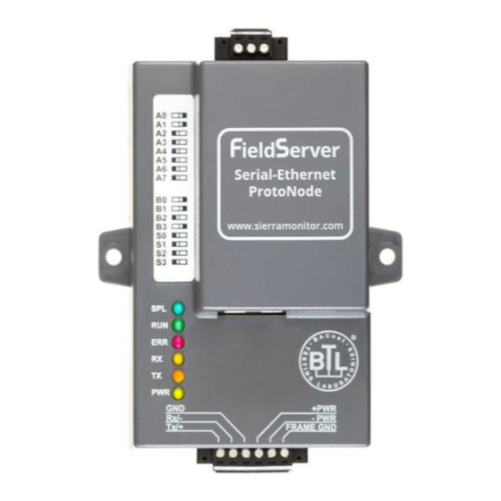
TROUBLESHOOTING LED Diagnostics Please see the diagram below for ProtoNode RER BACnet and LER LonWorks LED Locations. Diagnostic LEDs Description The SPL LED will light if the ProtoNode is off line. The RUN LED will start flashing 20 seconds after power indicating normal operation. The SYS ERR LED will go on solid 15 seconds after power up. -
Page 31: No Communication" Troubleshooting Trees
“No Communication” Troubleshooting Trees 6.2.1 General Troubleshooting Whenever a setting is changed (i.e. dipswitches or communication) power should be cycled to the ProtoNode to allow for settings to take effect. 1. Is power connected to boilers and ProtoNode? • Green PWR LED solid on ProtoNode •... -
Page 32: Metasys N2 Troubleshooting
6.2.4 Metasys N2 Troubleshooting 1. Are the “S Bank” Dipswitches set to Metasys N2? (See section 2.2.1) 2. Is the wiring to the EMS Network Correct? (See section 3.11) 6.2.5 Lonworks troubleshooting 1. Is the wiring to the EMS Network Correct? (See section 4.1) 2. - Page 33 Take Diagnostic Capture with FieldServer Utilities (continued) • The Default IP Address of the ProtoNode is 192.168.1.24, Subnet Mask is 255.255.255.0. If the PC and the ProtoNode are on different IP Networks, assign a static IP Address to the PC on the 192.168.1.xxx network.
- Page 34 Take Diagnostic Capture with FieldServer Utilities (continued) Click the + to add the ProtoNode Enter the Protonode’s IP address. • Step 1: Take a Log o Click on the diagnose icon of the desired device. Page 34 of 48 Universal Gateway Instruction Manual...
- Page 35 Take Diagnostic Capture with FieldServer Utilities (continued) o Select full Diagnostic o If desired, the default capture period can be changed. o Click on Start Diagnostic o Wait for Capture period to finish. Diagnostic Test Complete window will appear. o If Diagnostic Test Complete window does not appear after “Set Capture Period” is over, the diagnostic log may be found in the FieldServer directory (likely on the computer’s C Drive or under Program Files) : ▪...
- Page 36 Take Diagnostic Capture with FieldServer Utilities (continued) o Choose open to launch explorer and have it point directly at the correct folder. Send the Diagnostic zip file to support@fieldserver.com o If Diagnostic Test Complete window does not appear after “Set Capture Period” is over, the diagnostic log may be found in the FieldServer directory (likely on the computer’s C Drive or under Program Files) : ▪...
-
Page 37: Protonode Information
PROTONODE INFORMATION Specifications and Ordering Information ProtoNode RER BACnet ProtoNode LER LonWorks BACnet MS/TP, BACnet/IP, Protocol Metasys N2 Open, or LonWorks Modbus TCP ProtoNode Part Number: 106416-01 Part Number: 106418-01 Part Number FieldServer #: FPC-N34-0816 FieldServer #: FPC-N35-0817 One 6-pin Phoenix connector, one One 6-pin Phoenix connector, RS-485 +/- ground port, power +/- one RS-485 +/- ground port,... -
Page 38: Protonode Detailed View
ProtoNode Detailed View Page 38 of 48 Universal Gateway Instruction Manual... -
Page 39: Appendix A. Pfc 2000-4000 With Honeywell Control Points List
PFC 2000-4000 with Honeywell Control Points List Appendix A. BACnet, N2 and LonWorks Points BACnet LonWorks Read/ Data Data Data Write Point Name Type Type Addr Lon Name Lon SNVT Type Burner On Off nvi/nvoBrnrOnOff_XXX SNVT_switch Demand Source nvoDem_Src_XXX SNVT_count_f... - Page 40 Modbus Points Modbus Protocol Read/ Description Register Name Write Enable / Disable CH Modbus STAT 0 = no demand 1 = demand When this register is not written every “Modbus 400,577 CH Modbus Stat Command Time Out” parameter seconds (default 30 seconds), CH Modbus Stat is reverted to 0, no demand.
- Page 41 Modbus Protocol Read/ Description Register Name Write 0=Unknown, 1=Normal setpoint, CH setpoint 2=TOD setpoint, 410,065 source 3=Outdoor reset, 4=Remote control (4-20mA ), 7=Outdoor reset time of day -40 F (-40°C) to 266 F (130°C) Active CH 410,016 Setpoint determined by CH setpoint source setpoint (register 65).
- Page 42 Modbus Protocol Read/ Description Register Name Write Building Automation may send the controller the outdoor air temperature. Use this register to change the outdoor temperature. When this register is not written every “Modbus Command Outdoor Time Out” parameter seconds (default 30 410,817 Temperature seconds), temperature is set to bad data quality...
- Page 43 Modbus Protocol Read/ Description Register Name Write Reason for burner hold None Anti short cycle Boiler Safety Limit Open Boiler Safety Limit Open, (ILK Off) Return sensor fault Supply sensor fault DHW sensor fault Stack sensor fault 410,040 Hold code Ignition failure Flame rod shorted to ground Delta T inlet/outlet high...
- Page 44 Status Description Note Forced On from manual pump control Forced On due to Outlet high limit is active Forced On from burner demand Forced On due to Lead Lag slave has demand Forced Off from local DHW priority service Forced Off from Lead Lag DHW priority service Forced Off from Central Heat anti-condensation Forced Off from DHW anti-condensation Forced Off due to DHW high limit is active...
-
Page 45: Appendix B. "A" Bank Dip Switch Settings
“A” Bank DIP Switch Settings Appendix B. Address Address Page 45 of 48 Universal Gateway Instruction Manual... - Page 46 Address Address Page 46 of 48 Universal Gateway Instruction Manual...
- Page 47 Address Address Page 47 of 48 Universal Gateway Instruction Manual...
- Page 48 Universal Gateway Instruction Manual PFC8212 R0 Page 48 of 48 Universal Gateway Instruction Manual...
Need help?
Do you have a question about the PFC 2000-4000 and is the answer not in the manual?
Questions and answers