Table of Contents
Advertisement
Quick Links
Advertisement
Table of Contents

Summary of Contents for Ecolab EFW5L
- Page 1 Ecolab Fluid Warmer EFW5L Operator’s Manual Page 1 of 51 EFW5L_IFU REV NEW...
-
Page 2: Table Of Contents
Specifications ........................10 Operating Characteristics ....................15 Power Connection ........................16 Temperature Control System ...................... 16 EFW5L Drapes ..........................16 Assembly Instructions .....................16 Assembling EFW5L ........................16 Controls, Indicators, and Components ................17 Locks the wheels to prevent unintended movement of the unit............18 Installation and Setup ......................20... - Page 3 Powering On ..........................42 Powering Off ........................... 42 Controller ..........................43 7.3.1 Home Screen Display ......................... 43 7.3.2 Warnings ............................ 44 Basic Operation ........................45 Post Procedure and Storage Steps ..................46 Power Interruption ......................... 46 Troubleshooting .......................47 Maintenance ........................49 9.1 Routine Cleaning After Each Use ......................
-
Page 4: Introduction
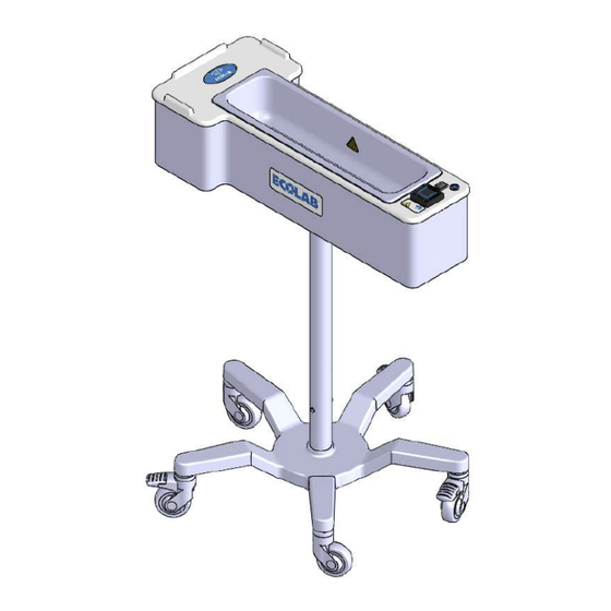
1 Introduction Intended Use / Indications for Use The Ecolab Fluid Warmer (EFW5L) is designed to warm and maintain the temperature of surgical solutions prior to their use. The Ecolab Pillow Drape (EPD400/EPD400N) is a single-use equipment cover intended for use where warm irrigation is required. - Page 5 Symbol Symbol Title Standard Title Reference (Symbol Description) Global Trade Item Number (GTIN) Identifies the unique GTIN associated with the product. Medical Device Indicates that this item is a medical device. Importer name Any natural or legal person established within the Union that places a device on the Union market.
- Page 6 Volume Indicates the fluid volume capacities for the basin. ETL listed mark Certifies that EFW5L conforms to IEC 60601-1 3rd Edition Standard as tested by a 3rd Party Laboratory. Indicates that this is where the pillow drape and NFC tag should be placed.
- Page 7 Symbol Symbol Title Standard Title Reference (Symbol Description) Serial number Medical devices - ISO 15223-1 Symbols to be used Reference #5.1.7 Indicates the manufacturer’s serial number so with medical device that a specific medical device can be FDA Recognition labels, labelling and identified.
- Page 8 - Part 1: General requirements FCC Certification Mark Radio Frequency Title 47 CFR Part Devices Certifies that EFW5L has been tested and found to be in compliance with Federal Communication Commission (FCC) standards. Page 8 of 51 EFW5L_IFU REV NEW...
-
Page 9: Warnings And Precautions
EFW5L is not designed for use, transport, or storage in the presence of flammable • anesthetics Position EFW5L to allow for easy removal of power cord from power outlet. Power cord • must be disconnected from outlet to isolate EFW5L from external power supply. -
Page 10: Specifications
Warning: Portable RF communications equipment (including peripherals such as • antenna cables and external antennas) should be used no closer than 30 cm (12 inches) to any part of the EFW5L including cables specified by the manufacturer. Otherwise, degradation of the performance of this equipment could result. •... - Page 11 Guidance and manufacturer’s declaration – electromagnetic emissions EFW5L is intended for use in the electromagnetic environment specified below. The customer or the user of EFW5L should assure that it is used in such an environment. Emissions test Compliance Electromagnetic environment –...
- Page 12 Portable and mobile RF communications equipment field IEC should be used no closer to any part of EFW5L 61000-4-8 including cables, than the recommended separation distance calculated from the equation applicable to the frequency of the transmitter.
- Page 13 Proximity 65A/m (rms), PM at 65A/m (rms), PM Magnetic 2.1 kHz, at 2.1 kHz, Fields IEC 50% duty cycle, 50% duty cycle, 61000-4-39 134.2kHz; 134.2kHz; 7.5A/m (rms), PM at 7.5A/m (rms), PM 50 kHz, at 50 kHz, 50% duty cycle, 50% duty cycle, 13.56MHz 13.56MHz...
- Page 14 RF transmitters, an electromagnetic site survey should be considered. If the measured field strength in the location in which EFW5L is used exceeds the applicable RF compliance level above, EFW5L should be observed to verify normal operation. If abnormal performance is observed, additional measures may be necessary, such as re- orienting or relocating EFW5L.
-
Page 15: Operating Characteristics
• Minimum fluid Set Point temperature: 20°C (68°F) • Warmer Basin fluid volume for use: 1.0-4.5 L • Language supported: English Wheel Locks: Locks the wheels to prevent unintended movement of EFW5L. • Page 15 of 51 EFW5L_IFU REV NEW... -
Page 16: Power Connection
Power Cord Hook: Provides storage for power cord when EFW5L is not in use. • Power Connection The EFW5L is a dual voltage system designed to work when connected to a 120 or 230 VAC 50/60 Hz Power Source. Temperature Control System To ensure the safe use of warm fluid, the basin heater controls may be set at a temperature between 20°C and 49°C (68°F and 120°F) by the user. -
Page 17: Controls, Indicators, And Components
Column to the Base. Figure 1: Assembly 5 Controls, Indicators, and Components Refer to Figure 2. This section provides a quick description of the controls, indicators, and components of EFW5L. Page 17 of 51 EFW5L_IFU REV NEW... -
Page 18: Locks The Wheels To Prevent Unintended Movement Of The Unit
Item Name Description Power Indicator Light Blue LED that lights up when the warmer system is emitting diode (LED) turned on. Power Switch Controls power to the warmer system. Controller Shows Set Point temperature, Current fluid temperature, and error messages during operation. + Button Button on the controller used to increase Set Point temperature and to scroll between selections in... - Page 19 Figure 2: Controllers, Indicators, and Comonents Refer to Figure 3. The home screen displays the Current fluid temperature (1) on the upper display in red font and the Set Point temperature (2) on the lower display in green font in the selected temperature scale (°F or °C).
-
Page 20: Installation And Setup
Remove fluid from EFW5L basin before moving. b. Keep hold of the Handle on the EFW5L unit at all times during movement. c. Be sure that the floor area near EFW5L is free from cables, cords, thresholds, or any other obstructions. -
Page 21: Connecting And Disconnecting The Power Cord
Refer to Figure 5. Connect the power cord as follows: a. Locate the Power Cord Kit. b. Locate female end with red locking button (1) and plug it into EFW5L power inlet (2). You should hear an audible click when plug is secured. -
Page 22: Fuse Installation
Pull back red lock button (5) and disengage female end from EFW5L. Figure 5: Connecting and Disconnecting the Power Cord Fuse Installation Procedures described in this section should only be performed by qualified service personnel. Refer to Figure 6. Install the fuses as follows: a. -
Page 23: Initial Setup
Figure 6: Fuse Installation Initial Setup Follow the steps below for initial setup of the warmer system. All of the settings referenced in this section will remain set when EFW5L is turned off and then turned back on. 6.6.1 Temperature Scale Function Temperature readings can be displayed in either Fahrenheit or Celsius. - Page 24 b. Press the right arrow button to enter the Display Units submenu. – c. Press the “+” or “ ” buttons to scroll up or down to select °C or °F. The scale selected will be in red font. Note: The temperature scale cannot be changed if the Set Point temperature is locked.
-
Page 25: Adjusting Set Point Temperature
6.6.2 Adjusting Set Point Temperature The home screen displays the Current fluid temperature (1) on the upper display in red font and the Set Point temperature (2) on the lower display in green font in the selected temperature scale (°F or °C). The Set Point temperature can be adjusted by the user. Note: If the Set Point was requested to be locked by the factory, the ability to adjust the Set Point by the user is disabled. -
Page 26: Locking And Unlocking The Set Point Temperature Controls
a. From the home screen, Press the “+” button to increase the Set Point temperature by increments of 1 degree. Press the “–” button to decrease the Set Point temperature by increments of 1 degree. Press and hold the “+” or “–” buttons to adjust the Set Point Temperature ... - Page 27 c. Press the “–” button to scroll down to “Factory” (“Factory” will be in a red font when selected). d. Press the right arrow button to enter the Factory submenu (“Lock” will be selected in a red font). e. Press the right arrow button to enter the Lock 1 submenu (“Operations Page” will be selected in a red font.) Press the right arrow button to enter the Operations Page submenu.
- Page 28 g. Ensure that the number displayed is set to “3.” If it is not, press the “+” or “–” buttons to increase or decrease the number displayed until it is set to “3.” h. Press the right arrow button to enter the Password Enable submenu. (“Off” will be selected in a red font.) Press the right arrow button to enter the Read Lock submenu.
-
Page 29: Unlocking The Set Point Temperature
Ensure that the number displayed is set to “0.” If it is not, press the “+” or “–” buttons to increase or decrease the number displayed until it is set to “0.” (Note: If the screen flashes, you may have scrolled too far and the number will not save. If so, press the home button to return to the home screen and repeat steps a-l.) (Note: When the set point temperature is locked (write security is set to 0), the temperature scale, password enable, and set point temperature range features are also... - Page 30 c. Press the right arrow button to enter the Factory submenu. (“Lock” will be selected in a red font). d. Press the right arrow button to enter the Lock 1 submenu. (“Operations Page” will be selected in a red font.) e.
- Page 31 Ensure that the number displayed is set to “3.” If it is not, press the “+” or “–” buttons to increase or decrease the number displayed until it is set to “3.” g. Press the right arrow button to enter the Password Enable submenu. (“Off” will be selected in a red font.) h.
-
Page 32: Setting A New Set Point Temperature Range Within The Factory Set Point Temperature Range
Press the home button to return to the home screen with the Set Point temperature now unlocked. m. To confirm that the Set Point temperature is successfully unlocked, press the “+” or “–” buttons to attempt to increase or decrease the Set Point temperature. The Set Point temperature should change. - Page 33 c. Press the right arrow button to enter the Minimum Set Point submenu. d. Press the “+” or “–” buttons to increase or decrease the number displayed, until the desired Minimum Set Point is shown. The user cannot set this value below 68°F (20°C). e.
-
Page 34: Enabling And Disabling Password Protection
g. Press the home button to return to the home screen with the Set Point Temperature range now updated. 6.6.7 Enabling and Disabling Password Protection Enabling the password provides a second layer of security on the unit. If the password is enabled, the user will be prompted for the password before any setting changes can be made. - Page 35 d. Press the right arrow button to enter the Lock 1 submenu. (“Operations Page” will be selected in a red font.) e. Press the “–” button to scroll down to “Password Enable” (“Password Enable” will be in a red font when selected). Press the right arrow button to enter the Password Enable submenu.
-
Page 36: Disabling Password Protection
g. Press the “–” button to scroll down to “On” (“On” will be in a red font when selected). h. Press the home button to return to the home screen with the Password now enabled. 6.6.9 Disabling Password Protection (Note: If the set point temperature is locked (write security is set to 0), the password enable/disable feature is also locked and cannot be adjusted. - Page 37 b. Press the “–” button to scroll down to “Factory” (“Factory” will be in a red font when selected). c. Press the right arrow button to enter the Factory submenu. (“Lock” will be selected in a red font). d. Press the “–“ button to scroll down to “Unlock” (“Unlock will be in red font when selected).
- Page 38 e. Press the right arrow button to enter the Unlock submenu. (“Public Key” will be selected in a red font. Press the “–” button to scroll down to “Password” (“Password” will be in a red font when selected). g. Press the right arrow button to enter the Password submenu. Ensure that the number displayed is set to “156”.
- Page 39 h. From the home screen, press the right arrow button to navigate to the Operations menu. (“Display Units 1” will be selected in a red font). Press the “–” button to scroll down to “Factory” (“Factory” will be in a red font when selected).
- Page 40 Press the “–” button to scroll down to “Password Enable” (“Password Enable” will be in a red font when selected). m. Press the right arrow button to enter the Password Enable submenu. (“On” will be selected in a red font.) n.
-
Page 41: Changing Touchpad Sensitivity
o. Press the home button to return to the home screen with the Password feature now disabled. 6.6.10 Changing Touchpad Sensitivity a. From the home screen, press the right arrow button to navigate to the Operations menu. (“Display Units 1” will be selected in a red font). b. -
Page 42: Operating Instructions
2. The Power Switch on top of the unit is used to turn on the system. Press the on side of the Power Switch (1) to power on the unit. The blue Power Indicator LED (2) will remain lit as long as the on side of the Power Switch was pressed and EFW5L is plugged in. -
Page 43: Controller
“Alarm 2” will begin flashing. See Section 7.3.2 for details. The number “5” (6) in red font indicates the state of the drape. When displayed, the unit has successfully detected an Ecolab drape. Page 43 of 51... -
Page 44: Warnings
When not displayed, the drape is either not installed, installed incorrectly, or expired. The temperatures on the home screen, as shown in Figure 6, can be displayed in either degrees Celsius or degrees Fahrenheit (Section 6. 5.1).. Figure 8: Controller Home Screen Display 7.3.2 Warnings In the event that the Current fluid temperature exceeds the Set Point temperature ... -
Page 45: Basic Operation
Ensure unit is off and basin is dry before draping. e. Install an Ecolab EPD400 or EPD400N drape. Adjust drape to ensure uniform contact with the basin walls (i.e. no folds that create air pockets) and NFC tag is centered over NFC label on shelf. -
Page 46: Post Procedure And Storage Steps
Unplug male end of Power Cord (1) from wall outlet. e. Store Power Cord on Power Cord Hook (2). Allow EFW5L warmer basin to cool down completely (approx. 5 minutes) and follow cleaning procedures as described in Section 9.1. -
Page 47: Troubleshooting
Symptom Probable Cause Action Power cord not Inspect power cord and verify that it is EFW5L will not power plugged in properly properly connected to the unit and on. The Power plugged in to the wall outlet. Indicator Light is not No power at wall Verify that wall outlet power is turned on;... - Page 48 Controller malfunction Contact customer service. Wheel locks broken or Faulty wheel locks Contact customer service. do not secure EFW5L in place. Crack or damage to EFW5L unit was Remove the unit from service. Contact EFW5L enclosure. damaged customer service.
-
Page 49: Maintenance
Procedures described in this section should only be performed by qualified service personnel. 9.1 Routine Cleaning After Each Use a. Clean the EFW5L as follows: a. Always allow the basin to cool down completely (approx. 5 minutes) before cleaning b. Clean and dry the basin after each use with a lint free cloth and isopropyl alcohol. -
Page 50: Monthly Maintenance
Install a single-use EPD400 or EPD400N Drape. b. Add one (1) liter of saline or water to the basin. c. Turn on EFW5L by pressing the “on” side of the Power Switch and allow to heat for one (1) hour. -
Page 51: Contact Information
CONSEQUENTIAL, INCIDENTAL, AND/OR SPECIAL DAMAGES. Ecolab reserves the right to discontinue products, change specifications, designs, terms, and conditions of sale without prior notice. Ecolab’s acceptance of buyer’s order is expressly limited to the terms and conditions contained herein. If a buyer subsequently...
Need help?
Do you have a question about the EFW5L and is the answer not in the manual?
Questions and answers