Table of Contents
Advertisement
Quick Links
For spare parts drawings refer to the document "LIST OF COMPONENTS" to be requested from the manufacturer.
• For any further information please contact your local dealer or call:
Phone (+39) 051 6781511 - Fax (+39) 051 846349 - e-mail: aftersales.emea@vsgdover.com
2510-M001-04_B
BUWS101 - BUWS101I
BUWS102 - BUWS102I
BUWS103 - BUWS103I
BUWS101U - BUWS101IU
BUWS102U - BUWS102IU
BUWS103U - BUWS103IU
INSTRUCTION MANUAL
TRANSLATION FROM THE
GB
ORIGINAL INSTRUCTIONS
VEHICLE SERVICE GROUP ITALY S.r.l
Via Filippo Brunelleschi, 9 - 44020 Ostellato - Ferrara - Italy
2510-M001-04_B
- Rev. n. 04 (01/2024)
Advertisement
Table of Contents

Subscribe to Our Youtube Channel
Related Manuals for Dover VSG BUWS101

Summary of Contents for Dover VSG BUWS101
- Page 1 2510-M001-04_B BUWS101 - BUWS101I BUWS102 - BUWS102I BUWS103 - BUWS103I BUWS101U - BUWS101IU BUWS102U - BUWS102IU BUWS103U - BUWS103IU INSTRUCTION MANUAL TRANSLATION FROM THE ORIGINAL INSTRUCTIONS For spare parts drawings refer to the document “LIST OF COMPONENTS” to be requested from the manufacturer. •...
-
Page 2: Table Of Contents
2510-M001-04_B INSTRUCTION, USE AND MAINTENANCE MANUAL Page 2 of 45 BUWS101 - BUWS101I - BUWS102 - BUWS102I - BUWS103 - BUWS103I - BUWS101U - BUWS101IU - BUWS102U - BUWS102IU - BUWS103U - BUWS103IU SUMMARY SYMBOLS USED IN THE MANUAL ________ 6 13.0 DEVICE FOR AUTOMATIC GLASS CLEANING (ON DEMAND) __________ 24 1.0 GENERAL INTRODUCTION __________ 9... - Page 3 2510-M001-04_B INSTRUCTION, USE AND Page 3 of 45 MAINTENANCE MANUAL BUWS101 - BUWS101I - BUWS102 - BUWS102I - BUWS103 - BUWS103I - BUWS101U - BUWS101IU - BUWS102U - BUWS102IU - BUWS103U - BUWS103IU Table D - Installation diagram lh base with Table G - Connection diagram electrical air _________________________________41 cables for FDA _____________________44...
- Page 4 2510-M001-04_B INSTRUCTION, USE AND MAINTENANCE MANUAL Page 4 of 45 BUWS101 - BUWS101I - BUWS102 - BUWS102I - BUWS103 - BUWS103I - BUWS101U - BUWS101IU - BUWS102U - BUWS102IU - BUWS103U - BUWS103IU Fig. 1 - BUWS101 - BUWS102 - BUWS103 - BUWS101U - BUWS102U - BUWS103U RUNNING DIRECTION 1 –...
- Page 5 2510-M001-04_B INSTRUCTION, USE AND Page 5 of 45 MAINTENANCE MANUAL BUWS101 - BUWS101I - BUWS102 - BUWS102I - BUWS103 - BUWS103I - BUWS101U - BUWS101IU - BUWS102U - BUWS102IU - BUWS103U - BUWS103IU Fig. 2 - BUWS101I - BUWS102I - BUWS103I - BUWS101IU - BUWS102IU - BUWS103IU RUNNING DIRECTION 1 –...
-
Page 6: Symbols Used In The Manual
2510-M001-04_B INSTRUCTION, USE AND MAINTENANCE MANUAL Page 6 of 45 BUWS101 - BUWS101I - BUWS102 - BUWS102I - BUWS103 - BUWS103I - BUWS101U - BUWS101IU - BUWS102U - BUWS102IU - BUWS103U - BUWS103IU SYMBOLS USED IN THE MANUAL Symbols Description Symbols Description Mandatory. - Page 7 2510-M001-04_B INSTRUCTION, USE AND Page 7 of 45 MAINTENANCE MANUAL BUWS101 - BUWS101I - BUWS102 - BUWS102I - BUWS103 - BUWS103I - BUWS101U - BUWS101IU - BUWS102U - BUWS102IU - BUWS103U - BUWS103IU INFORMATION PLATE LOCATION TABLE Only for BUWS101 - BUWS101I - BUWS102 - BUWS102I - BUWS103 - BUWS103I RUNNING DIRECTION RUNNING DIRECTION Only for BUWS101U - BUWS101IU - BUWS102U - BUWS102IU - BUWS103U - BUWS103IU...
- Page 8 2510-M001-04_B INSTRUCTION, USE AND MAINTENANCE MANUAL Page 8 of 45 BUWS101 - BUWS101I - BUWS102 - BUWS102I - BUWS103 - BUWS103I - BUWS101U - BUWS101IU - BUWS102U - BUWS102IU - BUWS103U - BUWS103IU BUWS101 - BUWS101I BUWS101U - BUWS101IU BUWS102 - BUWS102I BUWS102U - BUWS102IU Code numbers of plates 20331...
-
Page 9: General Introduction
2510-M001-04_B INSTRUCTION, USE AND Page 9 of 45 MAINTENANCE MANUAL BUWS101 - BUWS101I - BUWS102 - BUWS102I - BUWS103 - BUWS103I - BUWS101U - BUWS101IU - BUWS102U - BUWS102IU - BUWS103U - BUWS103IU INTENDED USE SOME OF THE PICTURES AND/ OR DISPLAY SCREEN PAGES The equipments covered by this manual and their PRESENT IN THIS MANUAL HAVE... -
Page 10: Safety Devices
2510-M001-04_B INSTRUCTION, USE AND MAINTENANCE MANUAL Page 10 of 45 BUWS101 - BUWS101I - BUWS102 - BUWS102I - BUWS103 - BUWS103I - BUWS101U - BUWS101IU - BUWS102U - BUWS102IU - BUWS103U - BUWS103IU SAFETY DEVICES Residual risks The machine was subjected to a complete analysis of PERIODICALLY, AT LEAST MONTH- risks according to reference standard EN ISO 12100. -
Page 11: General Safety Rules
2510-M001-04_B INSTRUCTION, USE AND Page 11 of 45 MAINTENANCE MANUAL BUWS101 - BUWS101I - BUWS102 - BUWS102I - BUWS103 - BUWS103I - BUWS101U - BUWS101IU - BUWS102U - BUWS102IU - BUWS103U - BUWS103IU GENERAL SAFETY RULES Only for BUWS101U - BUWS101IU - BUWS102U - BUWS102IU - BUWS103U - BUWS103IU WARNING AND INFORMATION PLATES HAVE BEEN APPLIED... -
Page 12: Packing And Mobilization For Transport
2510-M001-04_B INSTRUCTION, USE AND MAINTENANCE MANUAL Page 12 of 45 BUWS101 - BUWS101I - BUWS102 - BUWS102I - BUWS103 - BUWS103I - BUWS101U - BUWS101IU - BUWS102U - BUWS102IU - BUWS103U - BUWS103IU PACKING AND MOBILIZATION FOR • The workshop must be kept clean and dry. Make sure that the working premises are properly lit. -
Page 13: Fixtures Contained In The Packing
2510-M001-04_B INSTRUCTION, USE AND Page 13 of 45 MAINTENANCE MANUAL BUWS101 - BUWS101I - BUWS102 - BUWS102I - BUWS103 - BUWS103I - BUWS101U - BUWS101IU - BUWS102U - BUWS102IU - BUWS103U - BUWS103IU WORKING ENVIRONMENT CONDI- Fixtures contained in the packing TIONS The packing case contains also the fixtures box. -
Page 14: Lighting
2510-M001-04_B INSTRUCTION, USE AND MAINTENANCE MANUAL Page 14 of 45 BUWS101 - BUWS101I - BUWS102 - BUWS102I - BUWS103 - BUWS103I - BUWS101U - BUWS101IU - BUWS102U - BUWS102IU - BUWS103U - BUWS103IU EQUIPMENT ASSEMBLY Equipment’s utilization requires a usable space as indicated in Fig. -
Page 15: Anchoring System (To The Ground Through Small Blocks)
2510-M001-04_B INSTRUCTION, USE AND Page 15 of 45 MAINTENANCE MANUAL BUWS101 - BUWS101I - BUWS102 - BUWS102I - BUWS103 - BUWS103I - BUWS101U - BUWS101IU - BUWS102U - BUWS102IU - BUWS103U - BUWS103IU B U W S 1 0 2 - B U W S 1 0 2 I - B U W S 1 0 2 U - FOR WHAT CONCERNS CONNEC- TIONS’... -
Page 16: Assembly Procedures
2510-M001-04_B INSTRUCTION, USE AND MAINTENANCE MANUAL Page 16 of 45 BUWS101 - BUWS101I - BUWS102 - BUWS102I - BUWS103 - BUWS103I - BUWS101U - BUWS101IU - BUWS102U - BUWS102IU - BUWS103U - BUWS103IU Assembly procedures 1. Following RH - LH correct positioning, fix the plat- forms (Fig. - Page 17 2510-M001-04_B INSTRUCTION, USE AND Page 17 of 45 MAINTENANCE MANUAL BUWS101 - BUWS101I - BUWS102 - BUWS102I - BUWS103 - BUWS103I - BUWS101U - BUWS101IU - BUWS102U - BUWS102IU - BUWS103U - BUWS103IU 2. Fix the ramps (Fig. 6 ref. 1) to factory’s floor us- TO INSTALL NETWORK CABLES ing the supplied small blocks (M8) (Fig.
- Page 18 2510-M001-04_B INSTRUCTION, USE AND MAINTENANCE MANUAL Page 18 of 45 BUWS101 - BUWS101I - BUWS102 - BUWS102I - BUWS103 - BUWS103I - BUWS101U - BUWS101IU - BUWS102U - BUWS102IU - BUWS103U - BUWS103IU Fig. 7 For all the models 8. Following RH - LH correct positioning, mount plat- forms covers (Fig.
- Page 19 2510-M001-04_B INSTRUCTION, USE AND Page 19 of 45 MAINTENANCE MANUAL BUWS101 - BUWS101I - BUWS102 - BUWS102I - BUWS103 - BUWS103I - BUWS101U - BUWS101IU - BUWS102U - BUWS102IU - BUWS103U - BUWS103IU BUWS101I - BUWS102I - BUWS103I Fig. 9 BUWS101IU - BUWS102IU - BUWS103IU WHILE PERFORMING THE NEXT ASSEMBLY AND FLOOR FIXING...
- Page 20 2510-M001-04_B INSTRUCTION, USE AND MAINTENANCE MANUAL Page 20 of 45 BUWS101 - BUWS101I - BUWS102 - BUWS102I - BUWS103 - BUWS103I - BUWS101U - BUWS101IU - BUWS102U - BUWS102IU - BUWS103U - BUWS103IU TO INSTALL NETWORK CABLES Fig. 10 AND THE “TRAFFIC LIGHT” CA- BLE (IF SWS102A2 OR SWS102A3 ACCESSORIES PRESENT) CAR- RY OUT THE OPERATIONS DE-...
-
Page 21: Installation Of Kit For License Plate Recognition And Of "Traffic Light" Sys- Tem (Sws102A2)
2510-M001-04_B INSTRUCTION, USE AND Page 21 of 45 MAINTENANCE MANUAL BUWS101 - BUWS101I - BUWS102 - BUWS102I - BUWS103 - BUWS103I - BUWS101U - BUWS101IU - BUWS102U - BUWS102IU - BUWS103U - BUWS103IU 10.0 ELECTRICAL CONNECTIONS Installation of Kit for license plate rec- ognition and of “traffic light”... -
Page 22: Electrical Checks
2510-M001-04_B INSTRUCTION, USE AND MAINTENANCE MANUAL Page 22 of 45 BUWS101 - BUWS101I - BUWS102 - BUWS102I - BUWS103 - BUWS103I - BUWS101U - BUWS101IU - BUWS102U - BUWS102IU - BUWS103U - BUWS103IU Connect the camera kit (if present) to one of the free Only for BUWS102 - BUWS102U sockets of the switch and connect it to the electric sup- ply of the electrical panel (for BUWS102 - BUWS102U... -
Page 23: Kit For License Plate Auto
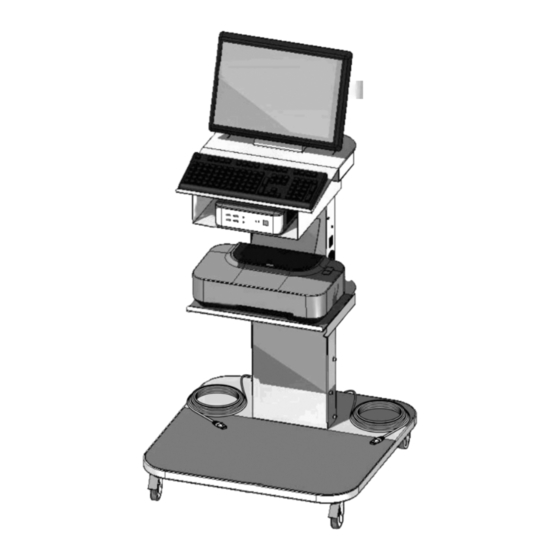
2510-M001-04_B INSTRUCTION, USE AND Page 23 of 45 MAINTENANCE MANUAL BUWS101 - BUWS101I - BUWS102 - BUWS102I - BUWS103 - BUWS103I - BUWS101U - BUWS101IU - BUWS102U - BUWS102IU - BUWS103U - BUWS103IU 11.0 KIT FOR LICENSE PLATE AUTOMAT- 12.0 CONTROL PANEL IC RECOGNITION AND FOR PRO- The equipment is provided with a keyboard to interact/ CEEDING “TRAFFIC LIGHT”... -
Page 24: Activation Smart Card
2510-M001-04_B INSTRUCTION, USE AND MAINTENANCE MANUAL Page 24 of 45 BUWS101 - BUWS101I - BUWS102 - BUWS102I - BUWS103 - BUWS103I - BUWS101U - BUWS101IU - BUWS102U - BUWS102IU - BUWS103U - BUWS103IU 13.0 DEVICE FOR AUTOMATIC GLASS 12.2 Activation smart card (only for BUWS101 - BUWS101I - BUWS102 - CLEANING (ON DEMAND) BUWS102I - BUWS101U - BUWS101IU... -
Page 25: Cover Air Mounting (Lh)
2510-M001-04_B INSTRUCTION, USE AND Page 25 of 45 MAINTENANCE MANUAL BUWS101 - BUWS101I - BUWS102 - BUWS102I - BUWS103 - BUWS103I - BUWS101U - BUWS101IU - BUWS102U - BUWS102IU - BUWS103U - BUWS103IU 13.1 Cover air mounting (LH) 13.2 Cover air mounting (RH) To mount the cover, follow the mounting procedure Repeat the same operations described in Par. -
Page 26: Switching The Machine Off
2510-M001-04_B INSTRUCTION, USE AND MAINTENANCE MANUAL Page 26 of 45 BUWS101 - BUWS101I - BUWS102 - BUWS102I - BUWS103 - BUWS103I - BUWS101U - BUWS101IU - BUWS102U - BUWS102IU - BUWS103U - BUWS103IU 15.0 VEHICLE TYRE DIAGNOSIS 14.2 Switching the machine off From “Home”... -
Page 27: Operations For Tread Profile's Diag- Nostic With Stand-Alone Profilometer (Buws101 - Buws101I - Buws101U - Buws101Iu)
2510-M001-04_B INSTRUCTION, USE AND Page 27 of 45 MAINTENANCE MANUAL BUWS101 - BUWS101I - BUWS102 - BUWS102I - BUWS103 - BUWS103I - BUWS101U - BUWS101IU - BUWS102U - BUWS102IU - BUWS103U - BUWS103IU 15.2 Operations for tread profile’s diag- Only for BUWS101U - BUWS101IU - BUWS102U nostic with stand-alone profilometer - BUWS102IU - BUWS103U - BUWS103IU (BUWS101 - BUWS101I - BUWS101U... -
Page 28: Operations For Tread Profile's Diag- Nostic With Profilometer In Reception Mode (Buws102 - Buws102I - Buws102U - Buws102Iu)
2510-M001-04_B INSTRUCTION, USE AND MAINTENANCE MANUAL Page 28 of 45 BUWS101 - BUWS101I - BUWS102 - BUWS102I - BUWS103 - BUWS103I - BUWS101U - BUWS101IU - BUWS102U - BUWS102IU - BUWS103U - BUWS103IU The following screen page will be displayed. 15.3 Operations for tread profile’s diagnos- tic with profilometer in reception mode Fig. -
Page 29: Operations For Tread Profile's Diagnos- Tic With Profilometer Connected To Car Diagnosis Line (Buws103 - Buws103I - Buws103U - Buws103Iu)
2510-M001-04_B INSTRUCTION, USE AND Page 29 of 45 MAINTENANCE MANUAL BUWS101 - BUWS101I - BUWS102 - BUWS102I - BUWS103 - BUWS103I - BUWS101U - BUWS101IU - BUWS102U - BUWS102IU - BUWS103U - BUWS103IU 15.4 Operations for tread profile’s diagnos- 15.5 Data bank tic with profilometer connected to car From the “Home”... -
Page 30: User Menu
2510-M001-04_B INSTRUCTION, USE AND MAINTENANCE MANUAL Page 30 of 45 BUWS101 - BUWS101I - BUWS102 - BUWS102I - BUWS103 - BUWS103I - BUWS101U - BUWS101IU - BUWS102U - BUWS102IU - BUWS103U - BUWS103IU 15.6 User menu 15.7 Assistance menu From the “Home” page (see Fig. 13) press From the “Home”... -
Page 31: Report Printing
2510-M001-04_B INSTRUCTION, USE AND Page 31 of 45 MAINTENANCE MANUAL BUWS101 - BUWS101I - BUWS102 - BUWS102I - BUWS103 - BUWS103I - BUWS101U - BUWS101IU - BUWS102U - BUWS102IU - BUWS103U - BUWS103IU 16.0 REPORT PRINTING IF THE DEVICE IS EQUIPPED WITH CAMERA, “PLATE”... -
Page 32: Complete Printing
2510-M001-04_B INSTRUCTION, USE AND MAINTENANCE MANUAL Page 32 of 45 BUWS101 - BUWS101I - BUWS102 - BUWS102I - BUWS103 - BUWS103I - BUWS101U - BUWS101IU - BUWS102U - BUWS102IU - BUWS103U - BUWS103IU 16.2 Complete printing The numerical values (Fig._19 ref._5) indicated on the tread’s profile indicate its “mm”... -
Page 33: Simplified Printing
2510-M001-04_B INSTRUCTION, USE AND Page 33 of 45 MAINTENANCE MANUAL BUWS101 - BUWS101I - BUWS102 - BUWS102I - BUWS103 - BUWS103I - BUWS101U - BUWS101IU - BUWS102U - BUWS102IU - BUWS103U - BUWS103IU 16.3 Simplified printing 16.4 Saving of test report Fig. -
Page 34: Troubleshooting Table
2510-M001-04_B INSTRUCTION, USE AND MAINTENANCE MANUAL Page 34 of 45 BUWS101 - BUWS101I - BUWS102 - BUWS102I - BUWS103 - BUWS103I - BUWS101U - BUWS101IU - BUWS102U - BUWS102IU - BUWS103U - BUWS103IU 17.0 TROUBLESHOOTING TABLE The possible troubles which might occur during equipment’s operation are listed below. The manufacturer disclaims all responsibility for damages to people, animals or objects due to improper operation by non- unauthorised personnel. -
Page 35: Routine Maintenance
2510-M001-04_B INSTRUCTION, USE AND Page 35 of 45 MAINTENANCE MANUAL BUWS101 - BUWS101I - BUWS102 - BUWS102I - BUWS103 - BUWS103I - BUWS101U - BUWS101IU - BUWS102U - BUWS102IU - BUWS103U - BUWS103IU 18.0 ROUTINE MAINTENANCE DO NOT STARE THE LASER BEAM DIRECTLY AT CLOSE RANGE BEFORE CARRYING OUT ANY ROU- WHILE THE EQUIPMENT IS OP-... -
Page 36: Dimensions
2510-M001-04_B INSTRUCTION, USE AND MAINTENANCE MANUAL Page 36 of 45 BUWS101 - BUWS101I - BUWS102 - BUWS102I - BUWS103 - BUWS103I - BUWS101U - BUWS101IU - BUWS102U - BUWS102IU - BUWS103U - BUWS103IU 19.1 Dimensions BUWS101 - BUWS102 - BUWS103 - BUWS101U - BUWS102U - BUWS103U 800 ÷... -
Page 37: Storing
2510-M001-04_B INSTRUCTION, USE AND Page 37 of 45 MAINTENANCE MANUAL BUWS101 - BUWS101I - BUWS102 - BUWS102I - BUWS103 - BUWS103I - BUWS101U - BUWS101IU - BUWS102U - BUWS102IU - BUWS103U - BUWS103IU 20.0 STORING 22.0 REGISTRATION PLATE DATA If storing for long periods disconnect the main power supply and take measures to protect the machine from dust build-up. - Page 38 Collar Network cable cameras mounting A (RJ45) Network cable cameras mounting B (RJ45) Network cable Collar cameras for the most distant base from the con- sole (only in the base closest to the con- sole) (RJ45) BUWS101 - BUWS101I - BUWS102 - BUWS102I - BUWS103 - BUWS103I - BUWS101U - BUWS101IU - BUWS102U - BUWS102IU - BUWS103U - BUWS103IU 2510-M001-04_B BASE INSTALLATION DIAGRAM NETWORK CABLE...
- Page 39 Collar “Traffic light” cable mounting A “Traffic light” cable mounting B Collar BUWS101 - BUWS101I - BUWS102 - BUWS102I - BUWS103 - BUWS103I - BUWS101U - BUWS101IU - BUWS102U - BUWS102IU - BUWS103U - BUWS103IU 2510-M001-04_B TRAFFIC LIGHT CABLE LAYING Page 39 of 45 Table N°B - Rev.
- Page 40 LH PLATFORM SENSOR white blue brown brown blue CONSOLE brown brown fairlead fairlead mounting A blue blue green-yellow green-yellow brown blue mounting A RH PLATFORM brown blue brown CONSOLE fairlead fairlead mounting B blue blue brown green-yellow brown blue mounting B 1 –...
- Page 41 * NOTE: the components in- dicated must be laid down during pro- filometer installation Compressed air net- Direction work * 2P Console-mamut cable CONSOLE only mounting A mounting A mounting A Remove when installing * Collar the profilometer mounting A only mounting A Remove when installing the * Collar...
- Page 42 * NOTE: the components in- dicated must be laid down during pro- filometer installation Towards LH BASE Towards LH BASE ASSEMBLY ASSEMBLY WITH AIR WITH AIR Remove when installing * 3P Mamut-mamut cable the profilometer * Collar * 2P Console-mamut cable Remove when mounting B installing the profilometer...
- Page 43 LH PLATFORM black black blue brown brown black blue black RH PLATFORM black black blue brown brown black blue black 1 – Profilometer card kit 2 – Laser extension cable 3 – 4P Mamut terminal board 4 – Micro assembly 5 –...
- Page 44 Profiler’s LED Collar Collar MAMUT-CARD cable see Table code 251090600 Proximity sensor cable see Table code 251090600 Laser power supply cable see Table code 251090600 MAMUT-CARD Connection for cable FDA version see Table code 251090600 B micro assembly A micro assembly Detail A Laser...
- Page 45 1 – ON-OFF switch 2 – RJ45 interface 3 – Ethernet wiring 4 – Cable press 5 – Ground cable 6 – Ground cable 7 – Smart card 8 – Ethernet wiring 9 – Pc 10 – Feeder 11 – 5 doors switch 12 –...
Need help?
Do you have a question about the VSG BUWS101 and is the answer not in the manual?
Questions and answers