
Summary of Contents for Sleepy Pony Labs Ammeter Clock
- Page 1 Ammeter Clock Information Assembly Guide Sleepy Pony Labs sleepyponylabs.com Document Revision 1 for Board Revision 1 & 2 For the latest updates, visit us at https://sleepyponylabs.com/...
-
Page 2: Specifications
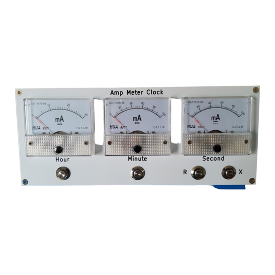
Welcome and thank you for purchasing the Ammeter Clock soldering kit from Sleepy Pony Labs! The Ammeter Clock is a controller board that can be connected to a set of ammeters (analog or digital) to turn them into a clock. - Page 3 Unpacking List / Bill of Materials (BOM) References Description Quantity C1 – C11 100nF Ceramic Capacitor C12, C13 22pF Ceramic Capacitor C14 – C16 1uF Ceramic Capacitor 470uF Electrolytic Capacitor R5 – R7, R13 – R15, 100 Ω Resistor R21 – R23, R26 – R28, R31 –...
- Page 4 Note: High-Resolution image of the PCB is on page 20. Note: We strongly recommended that you use the interactive BOM during unpacking and assembling. It will make your life much easier. It is available here: https://www.sleepyponylabs.com/ibom/html/ibom_ampmeter_clock_rev_1.html Optional Aluminum Front Panel If you bought an aluminum front panel from us, you will need additional hardware parts to buy that is not included with the front panel.
-
Page 5: Assembly Guide
Assembly Guide The general guide in soldering anything is to solder components with the lowest profile (least in height) first before soldering other taller components. This guide sums up my experience in soldering the board during the testing. Follow the steps here to reduce possible problems. Note: Before we proceed, since this kit contains SMD parts, I would like to give some recommendations first. - Page 6 1. MOSFET (SOIC-8) Align the MOSFET with the pads. The Pin-1 Mark on the chip should match the longer white line on the board. Hold the chip with tape then solder diagonal pins first so it will not move around (pin 4 and 8, or pin 1 and 5). Then solder the rest of the pins.
- Page 7 4. Resistor Arrays (HARD) Remove the parts from its packaging onto the board. Flip them so that the side with numbers is up. First, put small amount of solder on one corner pad, then use your tweezer to hold the resistor to the pad. Solder that pin and its diagonal pin first so it will not move around.
- Page 8 7. LED Remove the parts from its packaging onto the board. Check the polarity of the LED before you flip it. First, put small amount of solder on one pad, then use your tweezer to hold the resistor to the pad. Heat the pad up again until the solder flows to the part.
- Page 9 9. IC First, find the pin 1 mark. It will be a dimple or indent on one side of the chip. Align it with the notch marking on the board. Insert the chip into the holes. Be careful not to break any pin. Hold it in and solder two diagonal pins (for example, pin 1 and 8, or pin 7 and 14), then solder the rest of the pins.
- Page 10 12. Barrel Jack Insert it through the hole. Hold it with tape then solder it. Note: If you have a front panel, skip this part. 13. Screw Terminal Insert it through the hole. Hold it with tape then solder it.
-
Page 11: How To Use
How to Use First Power Up On the first power up, the LED indicators will light up randomly due to the POR (Power-On Reset) condition of the logic chips. Pressing the R button (Reset) should clear the counters and turn all of the LEDs off. If one or more buttons doesn’t work, check U3 (CD40106). - Page 12 Setting the Output Current Levels To make sure the ammeters are driven to the correct levels, the potentiometers need to be set up first. The setup is a repetitive process for all 19 potentiometers, and are as follows: 1. Identify the LED that matches the potentiometer to adjust. They will be in the same group and has the same number next to them.
- Page 13 Additional Instructions for Aluminum Front Panel and Enclosure 1. Secure the ammeters and the push buttons to the front panel using the hardware included with the ammeters and buttons. 2. Drill a hole in the back of the enclosure box. Install the DC jack with the hardware included with the jack.
-
Page 14: Troubleshooting
Troubleshooting In case your circuit does not work, the list below contains some possible causes of the issue from most likely to least likely: • Bad solder joints (Cold joints, Short between joints, Unconnected joints) • Incorrectly installed components (Wrong location or orientation) •... - Page 15 Schematics Note: On Rev.1 board, SW1 and SW2 are swapped.
- Page 20 PCB Layout Front...
Need help?
Do you have a question about the Ammeter Clock and is the answer not in the manual?
Questions and answers