Table of Contents
Advertisement
Advertisement
Table of Contents

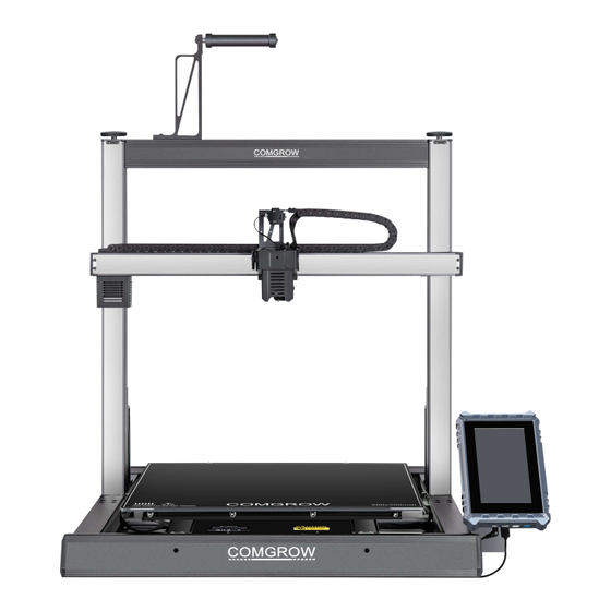
Summary of Contents for COMGROW T-500
-
Page 2: Table Of Contents
WELCOME TO COMGROW ! 1. Note Founded in 2017, Comgrow was formed by 2. Parameters people passionate about technology that helps you 3. Package List make things. With this deep-rooted dedication, we 4. Assembly wanted to make digital manufacturing processes... -
Page 3: Note
(used), abide by professional ethics, pay attention to safety obligations, and strictly prohibit the use of our products or equipment for any illegal purposes. Comgrow will not be responsible for any violators' legal liability under any circumstance. -
Page 4: Parameters
Parameters... -
Page 5: Package List
Package List Base Gantry Screen Screen holder Filament Filament Holder Support Base Accelerometer Power Cable Allen Wrench Slotted Phillips Diagonal Pliers Spatula Zip Tie Screwdriver screwdriver Nozzle Socket Spanner Spare Nozzle Tweezers Cleaner Neddle Flash Drive Cable clamp M3X30*2 M5X35*8 M5X10*2 M4X10*3 M3X6*4... -
Page 6: Assembly
Gantry 1. Install the gantry frame into the grooves on the left and right ends of the base. Use four M5X35 screws to secure each side, totaling eight screws. The extruder kit should face the front of the machine. Note that the machine components are heavy. -
Page 7: Cable Drag Chain
Cable Drag Chain The following are the corresponding points for the installation position of the Cable drag chain. 1. Lay the drag chain on the right as M3X6 shown, use two screws to install the drag chain at the end A 2. -
Page 8: Touchscreen
Touchscreen 1.First, attach the touch screen mounting plate to the back of the touch screen, M4X10 using three screws to secure it. 2.Then, install the entire touch screen assembly to the right front of the machine base, using the remaining two M5X10 screws to secure it. -
Page 9: Connect Wires
Connect Wires 1. X Motor 2. X Limit Switch 3. Extruder kit 4. Touchscreen 1&2 B(Either of the three) 5. Z1 Motor 6. Z2 Motor Please select the correct input voltage to match your local mains (230V or 115V). 7. -
Page 10: Accelerometer
Accelerometer The accelerometer is an optional module, you can choose whether to install it according to your needs 1. Please pay attention to the two screw holes here on the nozzle 2. Mount the accelerometer M3X16 here with two screws ... -
Page 11: Touchscreen
Touchscreen Power: DC 12~24V USB2.0 Type-C Press the Power button for more than 5s at USB3.0 Power power on status, the klipper system will closed. USB2.0 USB2.0X2 ... -
Page 12: Move, Temperature
Move Move Homing X+: Move X axis to right X-: Move X axis to left Y+: Move Y axis forward Y-: Move Y axis backward Z+: Move Z axis up Z-: Move Z axis down ... -
Page 13: Extruder, More
Extruder Extrude When temconnect to wifip is not enough, it is not allowed to have related operation about the extruder. 1. Nozzle real-time temperature,click*Temperature* to adjust temperature. 2. Extrude: extrude filament Retract: retract filament 3. Load: Execute a macro command to load filament. Unload: Execute a macro command to withdraw the ... -
Page 14: Bed Mesh, Z Calibrate
Bed Mesh Bed Mesh 1. Add profile 2. Clear the saved leveling data in current profile 3. Start calibrate 4. Leveling data preview 5. Current profile name 6. Delete current profile Z Calibrate Z Calibrate ... -
Page 15: Limits, Fan, Macros
Limits Limits Max Acceleration Max Deceleration Max Speed Square Corner Velocity Click the number on the right side of the value bar to enter the value manually We have adjusted to the best settings for you out of the factory, if you do not know these parameters very well, please do not change the parameters arbitrarily,... -
Page 16: Led, Console, Save Config, Klipperscreen
Led, Console Console Control the on and off of the nozzle LED Open console to check out or input the command Save config, KlipperScreen Save config Save the current configuration, the system will restart. Settings... -
Page 17: Network
Network Network 1. Choose a Wifi connection 2. After entering the password, click *save* on the top right, not *☑*on the right bottom. 3. When there shows “Connection”or after click *close* on the right bottom and back to wifi interface, it shows “(connected)”... -
Page 18: Bed Leveling
Bed Leveling 1. Click *Move* on the home page. 2. Click *Homing* 3. Click * Z Tilt*. The machine will detect the left and right sides of the hot bed, and automatically calibrate the level of the X-axis beam 4. After machine calibration 5. - Page 19 Bed Leveling 11. Click * More* on home page. 12. Click *Bed Mesh*, then click *Calibrate* after the detection is complete, restart the system, Leveling complete. If you want to view the bed mesh data later, please return to this interface and click the current configuration name "default“...
-
Page 20: Configuration
Change Configuration If you want to change the printer configuration, after entering the web page by IP, click the “configuration” option on the left menu bar Click the "Printer.cfg" file (the one without the date) to configure After the configuration is complete, click the "SAVE &... -
Page 21: Print
Print You can remotely upload files on the web Click "Print" on the main interface. page and print, or directly insert a U disk into the USB port on the display to print. Click the print icon or the STL thumbnail to print. - Page 22 SHENZHEN Comgrow Technology CO.,LTD. Official website :comgrow.com Email :service@comgrow.com...
- Page 23 FCC Statement This equipment has been tested and found to comply with the limits for a Class B digital device, pursuant to part 15 of the FCC Rules. These limits are designed to provide reasonable protection against harmful interference in a residential installation. This equipment generates, uses and can radiate radio frequency energy and, if not installed and used in accordance with the instructions, may cause harmful interference to radio communications.
Need help?
Do you have a question about the T-500 and is the answer not in the manual?
Questions and answers
How do I set the bed temperature of a T500 printer