Advertisement
Quick Links
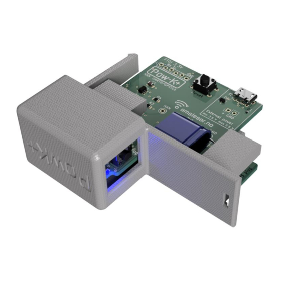
User Manual Pow-K / Pow-K+
Page 1 of 11
--------------------------------------------------------------------------------------------------------------------------------------
User Manual
Pow-K / Pow-K+
Version: 5
th
Jul 2023
Electronic version of this document is Document
This document is available as PDF in the webshop:
→ Product page → Vedlegg/Attachments
https://amsleser.no
Advertisement

Related Manuals for Amsleser Pow-K

Summary of Contents for Amsleser Pow-K
- Page 1 User Manual Pow-K / Pow-K+ Page 1 of 11 -------------------------------------------------------------------------------------------------------------------------------------- User Manual Pow-K / Pow-K+ Version: 5 Jul 2023 Electronic version of this document is Document This document is available as PDF in the webshop: → Product page → Vedlegg/Attachments...
-
Page 2: Table Of Contents
Technical specification ........................4 DIY kit assembly – tips and advice ....................4 Programming / flashing ........................6 Flashing a Pow-K+ (ESP32-S2) over USB cable ................ 6 Flashing a Pow-K (ESP8266) ....................6 Configuration and use ........................8 Installing the board in a Kamstrup HAN-NVE module ..............9... -
Page 3: Introduction
DIY kit builders (chapters 3 and 4). Before using the Pow-K/K+ you need to order activation of the HAN port from your local grid company. In Norway this can in most cases be done by logging in to "My page" / "Min side" on the website of the grid company, the port will then usually then be activated within 1-3 days. -
Page 4: Technical Specification
2 Technical specification To be written 3 DIY kit assembly – tips and advice The DIY kit includes a Pow-K PCB marked with layout version v1.3 and is based on ESP8266 (ESP- 12E/F) wifi module. • We recommend to first finalize and test the power part of the card: o Install J1, J3, C1, C2, U1: o Power J3 as indicated on the PCB. - Page 5 User Manual Pow-K / Pow-K+ Page 5 of 11 -------------------------------------------------------------------------------------------------------------------------------------- • D1 / RGB LED o Installed as shown below: o Be sure to install it in the right orientation. The longest lead is Vcc and shall be in the second hole from the bottom, as shown below.
-
Page 6: Programming / Flashing
Power the Pow-K card BEFORE attaching a powered FTDI module. If you connect a powered FTDI module to a non-powered Pow-K card, it could damage the ESP-12 module. If you are uncertain at this stage – this is maybe the time to back out and buy a ready-made board. - Page 7 User Manual Pow-K / Pow-K+ Page 7 of 11 -------------------------------------------------------------------------------------------------------------------------------------- • The card is not powered from the FTDI module, it must be powered on J3 before connecting the FTDI: • The card is set to programming mode by pressing and holding the PROG/AP button (S2) while pressing and releasing "ESP Reset"...
-
Page 8: Configuration And Use
If the card is started up before it is installed in the power meter it needs to be powered via connector J3 (DIY kit) or the USB contact (Pow-K+). Voltage: Minimum 3,5V, maximum 5,5V. (The USB connector will automatically deliver correct voltage.) Should the board see too high voltage, the voltage regulator U1 may get damaged –... -
Page 9: Installing The Board In A Kamstrup Han-Nve Module
User Manual Pow-K / Pow-K+ Page 9 of 11 -------------------------------------------------------------------------------------------------------------------------------------- 6 Installing the board in a Kamstrup HAN-NVE module The board can be installed to replace the original card of a Kamstrup HAN-NVE module: Procedure If the HAN-NVE module is installed in the meter: Pull it out horizontally. It may require some force. - Page 10 Page 10 of 11 -------------------------------------------------------------------------------------------------------------------------------------- Remove the original card, place it in the protective bag the Pow-K was delivered in – and store it safely with the meter. The card is held in position by four slots: Two in the bottom of the enclosure, two in the lid:...
- Page 11 Page 11 of 11 -------------------------------------------------------------------------------------------------------------------------------------- Position the Pow-K card on the lid, ensure it is seated in the slots: (Photo shows a previous version of the Pow-K card.) Place the enclosure over the card, pull lid and enclosure together until it snaps in place: Insert the module in the Kamstrup meter.
Need help?
Do you have a question about the Pow-K and is the answer not in the manual?
Questions and answers