Table of Contents
Advertisement
Quick Links
Advertisement
Table of Contents

Summary of Contents for Athlete SC-V Series
- Page 1 SC-V Series Pure Sine Wave Inverter User Manual (Version 2.5)
- Page 3 Preface This user manual contains proprietary information about installation, operation and usage of equipment which is protected by copyright. All rights are reserved. Please read this manual carefully before operation. Equipment should be operated by qualified personnel to ensure normal working. Please reserve this manual carefully for future reference. Marks The following marks and signs will be used in this product manual.
- Page 4 CONTENT Error! Bookmark not defined. Error! Bookmark not defined. Error! Bookmark not defined. Error! Bookmark not defined. Error! Bookmark not defined. Error! Bookmark not defined. 5.1. Error! Bookmark not defined. 5.2. Error! Bookmark not defined. 5.3. 5.4. Error! Bookmark not defined. 5.5.
-
Page 5: Product Introduction
SC-V series Inverter provides standby power to protect equipment and data when utilities fail or get abnormal. As an optional function, SC-V series Inverter communicates with local net servers and other computer system via RS232 communication sockets.RS232 socket provides information for main computer, such as voltage, current, temperature and frequency with Inverterilon2000 power management software. -
Page 6: Specification & Data
3. SPECIFICATION & DATA 6.25 12.5 MODEL: SC-V BATTERY adaptation √ √ √ √ ╳ ╳ ╳ ╳ ╳ ╳ ╳ ╳ √ √ √ √ √ √ √ √ ╳ ╳ ╳ ╳ √ √ √ √ √ √ √... - Page 7 Battery Anti-Polarity Protection High Temperature Protection ALARM Power Failure Battery Low Voltage Buzzer Sounds When Battery Voltage Is Down To 10.5/10.7v Per Battery (After 2nd Alarm) Inverter Failure Overload ENVIRONMENTAL Noise < 38 Db (1 Meter) Temperature 0 ~ 40℃ Humidity 10% ~ 90% (Non-Condensing) MANAGEMENT...
-
Page 8: Installation
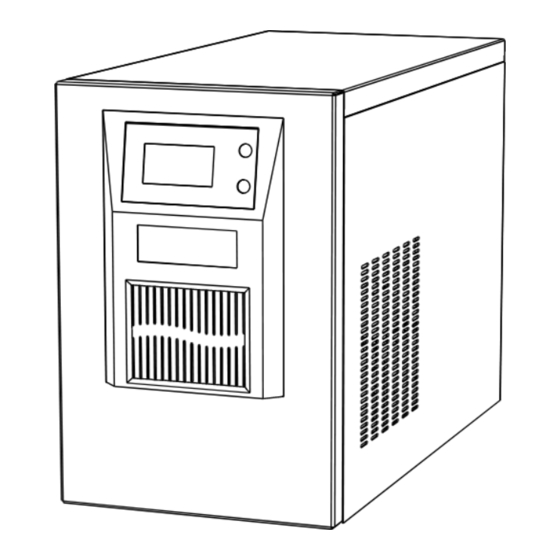
4. UNPACKING The unit is packed by firm caution in order to avoid possible damage during transportation. Please check that the packing is in good condition before initial use. Please contact with your supplier immediately if there is any damage on Inverter. ●... - Page 10 5.3. Appearance 2KVA 2.5KVA-5KVA...
- Page 11 6KVA-12.5KVA 5.4. Maximum Working Current & Recommend Cable Connection Recommended Cable Diameter Max capacity (VA) 1000 1500 2000 3000 5000 Max current input (A) 11.5 Diameter of input wire/mm 0.75 Max output current (A) 13.6 Diameter of output wire/mm 0.75 Diameter of ground 0.75 wire/mm...
- Page 12 ● The surrounding temperature should be less than 40℃. ● The cable can be thicker if the cable can't fit with the table above.
-
Page 13: Battery Connection
5.5. Battery Connection Danger Inverter below 6KVA has no battery anti-polarity protection. Please make sure to connect the batteries correctly. Otherwise, the devices will be damaged immediately. ● To connect Inverter with built-in battery, please refer to following schematic: ● To connect Inverter with external battery, please refer to following schematic... -
Page 14: Operation
6. OPERATION 1 Input Voltage Display 2 Output Voltage Display 3 ON Button 4 Battery Capacity Display 5 OFF Button 6 Abnormal Condition Display 7 Overload Display 8 Charging Status Display 9 Normal Status Display 10 Load Utilization Ratio display 6.1. - Page 15 the battery, and display “0” on “INPUT VOLTAGE”. If it beeps every 1sec, it means that the battery is empty; the Inverter will turn off soon. *Notice: Please don’t forget to charge the Inverter after using. 6.4. Launch ● Turn on the Inverter under City Power Mode. 1) If the city power is available and it connects to the Inverter, it will turn on automatically.
- Page 16 2) Click ON + OFF 10 seconds until the INPUT VOLTAGE display 992 loosen the button, the OUTPUT VOLTAGE in the display values for which kind of battery charging VOLTAGE. Inverter will display interface to adjust the charging voltage type. 3) According to the "ON or OFF"...
-
Page 17: Troubleshooting
*☼: the indicator light shines Notice: If the overload exceeds 10% under Battery Mode, it will be shut down in 30sec; if exceeds 20% and it will be shut down in 2sec. 8. SECURITY Properly Used ● Our equipment supplies the uninterruptible power to the load. ●... -
Page 18: Battery Maintenance
● Whether the device is under city power. ● Whether the input voltage or frequency is in rated range. ● Whether the circuit breaker is in good condition. ● If not, please contact your dealer with following information: ● Model number. ●... - Page 19 12. COMMUNICATION Communication Interface This series provide communicate port to realize the remote monitoring of Inverter. We can use USB, RS232 or intelligent slot (used with specialized WEBPOWER Card) as communication ports. They can provide information, such as voltage, current, temperature and frequency indicators, to monitor or control the Inverter.
Need help?
Do you have a question about the SC-V Series and is the answer not in the manual?
Questions and answers