Table of Contents
Advertisement
Quick Links
Advanced IP-KNX interface for KNX and/or
Control4 installations
Codes: EK-BT1-TP
Advanced IP-KNX interface for KNX and/or Control4
installations is a web-server designed to offer a suite
of connectivity and functional services to a Control4
supervision system, when used in combination with
ekinex KNX devices.
Description
The EK-BT1-TP server interface is designed for instal-
lation on DIN profile rail and occupies 2 modules. The
12-24 Vdc power supply is external (power supply not in-
cluded). The product with hardware based on embedded
operating system, has a KNX TP node (twisted pair) and
can therefore be connected directly to the bus network of
KNX devices. Connectivity as an IP gateway for Control4
is via the Ethernet port. The integrated web server built
with HTML5 technology allows access to the configura-
tion environment.
With EK-BT1-TP it is possible to:
• Send commands and receive information from KNX de-
vices in the CONTROL4 system
• Monitor the building energy consumption and control
loads accordingly with the overall absorption with a de-
dicated graphic driver for Composer
• Make a continuous diagnostic check on the KNX de-
vices and receive notifications in case of malfunctions
• Define command sequences (scenes) and execute
them with simple connections in Composer with 3rd
party drivers
• Perform logics configurable with a graphic editor and
executed in background
• Send notifications to CONTROL4 in case of malfun-
ctions or configurable events on the bus
Main features
• 12-24 Vdc power supply (absorption 240 mA at 12 Vdc)
by means of a special plug-in terminal supplied. Power
supply not included
• KNX TP bus (twisted pair) via red-black terminal pro-
vided
Technical Sheet STEKBT1TP_EN
• 1 Ethernet port via cat. 5 or higher cable and standard
RJ45 connector
• 1 RS485 port for future integrations
• 1 USB 2.0 port: for future integrations
• 2 frontal LEDs: POWER LED for signalling the pre-
sence of power supply; SERVICE LED for signalling
particular operations in progress
• 1 RESET button housed under the front cover on the
back of the vertical card
Other features:
• Plastic housing
• Design for mounting on 35 mm profile rail (according
to EN 60715)
• Degree of protection IP20 with product installed (accor-
ding to EN 60529)
• Insulation class II (according to EN 60335-1
• Climatic classification 3K5 (indoor, dry) and mechanical
3M2 (according to EN50491-2)
• Device weight: 120 g
• 2 UM modular device (1 UM = 18 mm)
• Dimensions 36 x 90.5 x 62 mm (W x H x D)
Environmental conditions:
• Operating temperature: 0°C ... + 40°C
• Storage temperature: - 10 ... + 70°C
• Transport temperature: - 10 ... + 70°C
• Relative humidity: 95% non-condensing
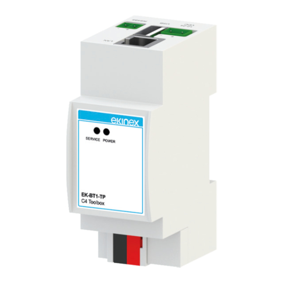
Operating, signaling and connection elements
EK-BT1-TP server is equipped with status LEDs, a RE-
SET button located under the front panel of the device,
terminals for power supply connection, KNX bus line and
Ethernet network. The server offers also an USB and
RS485 port, prepared for future use (not available at the
present moment in the configuration process).
6
8
7
4
1. LED SERVICE
2. LED POWER
3. RESET push-button
4. Clamp for power-supply 12-24 Vdc
5. Clamp for KNX bus
6. RJ45 Ethernet plug
7. Clamp for RS485 network
8. 2.0 USB port
Signaling elements
• POWER LED: indicates the presence of 12-24 Vdc po-
wer supply at terminals
• SERVICE LED: Normally off, steady mode or flashing
during IP address recovery sequences or factory re-
configurations
1
1
2
5
3
Advertisement
Table of Contents

Summary of Contents for KINEX EK-BT1-TP
- Page 1 • Transport temperature: - 10 ... + 70°C • Relative humidity: 95% non-condensing Operating, signaling and connection elements EK-BT1-TP server is equipped with status LEDs, a RE- SET button located under the front panel of the device, terminals for power supply connection, KNX bus line and Ethernet network.
- Page 2 • Max. torque 0.5 Nm of the vertical board at the bottom of the device towards the KNX terminals. Warning! The EK-BT1-TP interface is supposed to be connected to the same LAN as the CON- TROL4 controller(s); in case of different installa-...
- Page 3 • connect the EK-BT1-TP server to your PC via a “cross over” (or “crossover”) network cable • access your PC’s network settings, as illustrated in Enter the credentials of the user “admin” and confirm to...
- Page 4 If the configuration made makes it impossible to access The products described in this technical the EK-BT1-TP server or its correct use, it is possible to sheet at the end of its useful life are classi- restore the factory conditions, resetting the IP address fied as waste from electronic equipment ac- and emptying the supervision project using the “RESET”...
Need help?
Do you have a question about the EK-BT1-TP and is the answer not in the manual?
Questions and answers