
Summary of Contents for One Touch H700
- Page 1 PEB-3730 Main Board, 12.1 or 15 inch LCD’s...
- Page 2 Federal Communications Commission (FCC) This equipment has been tested and found to comply with the limits for a Class A digital device, pursuant to Part 15 of the FCC Rules. These limits are designed to provide reasonable protection against harmful interference in a residential installation. This equipment generates, uses, and can radiate radio frequency energy and, if not installed and used in accordance with the instructions, may cause harmful interference to radio communications.
- Page 3 Important Safety Information SAFETY INSTRUCTIONS Please read these safety instructions carefully. Keep this User manual for later reference. Disconnect this equipment from the AC outlet before cleaning. Don’t use liquid or spray detergent for cleaning. Use only a moistened sheet or cloth. For pluggable equipment, the socket-outlet should be installed near the equipment and should be easily accessible.
- Page 4 Copyright The information in this guide is subject to change without prior notice. The manufacturer shall not be liable for technical or editorial errors or omissions contained herein, nor for incidental or consequential damages resulting from the furnishing, performance, or use of this material. This manual contains information protected by copyright.
-
Page 5: Table Of Contents
Introduction Model H700 Characteristics ....................1 How to Use This Manual ....................... 2 A Quick Tour of Model H700 ....................3 Packing Check List ......................4 Dimensions 12.1”......................5 Dimensions 15”....................... 6 Connector Panels ........................7 Primary Connector Panel ....................7 Second Connector Panel.................... - Page 6 TouchKit Tools Installation ....................40 TouchKit Control Panel....................43 FIX COM PORT Tools Installation..................44 FIX COM Port Tools Installation for Windows XP ............44 Specification I/O board Configuration ....................... 47 9000PB0700 I/O Board Pin Definition ................47 9000PB0710 I/O Board Pin Definition ................51 9000PB0230 I/O Board Pin Definition ................
-
Page 7: Introduction
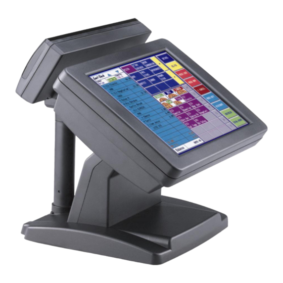
3730 Main Board Model H700 Characteristics Model H700 uses a high speed processor capable of handling a high capacity of data efficiently. Model H700’s solid quality Aluminum housing distinguishes it from ordinary plastic housings. The Model H700 touch terminal all-in-one design combines a powerful PC, multiple LCD and touch screens, which are suitable for any market. -
Page 8: How To Use This Manual
3730 Main Board How to Use This Manual This manual contains all the information you need to set up and use Model H700. In addition, you can also consult the manuals for the operating system and added hardware. Chapter 1 Introduction of Model H700 and the manual. -
Page 9: A Quick Tour Of Model H700
3730 Main Board A Quick Tour of Model H700 Before you start to set up the panel PC, take a moment to become familiar with the locations and purposes of the controls, drives, connectors and ports, which are illustrated in the figures below. -
Page 10: Packing Check List
Before you begin installation, please make sure that the following materials have been shipped: Main system with LCD panel Base ATX power supply Model H700 user’s guide 3730 motherboard user’s guide RJ-45 to DB9 RS-232 Cable for COM5 Utility and Motherboard chipset driver CD AC power cord If any of these items are missing or damaged, contact your distributor or sales representative immediately. -
Page 11: Dimensions 12.1
3730 Main Board Dimensions 12.1” Model H700 Dimensions Model H700 and MCR Dimensions Model H700 and VFD customer display... - Page 12 3730 Main Board Dimensions 15” Model H700 Dimensions Model H700 and MCR Dimensions Model H700 and VFD customer display...
-
Page 13: Connector Panels
The primary connector panel is located at the bottom of the main unit base. To clearly see the panel you must turn Model H700 upside down. Note: This configuration is for Model H700 units that have been supplied with an integral second LCD panel. I/O Port... -
Page 14: Second Connector Panel
Gladius H73X 3730 Second Connector Panel The second connector panel is located on the left side of the back of the main unit. It comes with a cover that needs to be removed to install a CD ROM Driver. I/O Port Connector Type Description The USB (Universal Serial Bus) port can be... -
Page 15: Hardware Setup
Model H700 Assembly Please make sure that the system power is turned off and the power supply is disconnected when make any hardware changes to Model H700. Remove the rear neck plate There are two I/O ports, 9000PB0700 and 9000PB0710, located on the back of the neck. The rear neck plate must therefore be removed before alterations can be made to the hardware. -
Page 16: Hard Disk Drive Installation
Gladius H73X 3730 Hard Disk Drive Installation Model H700 comes with an empty hard disk drive (HDD), unless a special request has been made. Installing a HDD 1. Turn off power and remove power cable from main unit. 2. Remove the Base/HDD Plate from the base (4 screws). -
Page 17: Compact Flash Installation
Gladius H73X 3730 Compact Flash Installation Model H700 will configure Compact Flash in IDE mode as secondary master after it is installed. The next available drive letter will be automatically assigned to Compact Flash. Installing Compact Flash 1. Turn off power and remove power cable from Model H700. -
Page 18: Magnetic Card Reader Installation
Gladius H73X 3730 Magnetic Card Reader Installation An optional Magnetic Card Reader (MCR) can be installed on the right side of Model H700. Magnetic Card Reader (MCR) Installing an MCR 1. Turn off system power. 2. Unplug the loopback from the MCR socket. The MCR socket is found on the right side on the back of the main Unit. - Page 19 Gladius H73X 3730 5. Turn on system power. Note: If the MCR does not work normally, please refer to troubleshooting Attention: The loopback or the MCR cable must be inserted in the socket for an external keyboard to function with Model H700.
-
Page 20: Mcr Parameter Modification
Gladius H73X 3730 MCR Parameter Modification This option is for users who need to customize the MCR parameters for a particular task. Some of the useful parameters include: The selection of country code, other than the default English. The choice of track combinations. iii. -
Page 21: Vfd Customer Display Installation
Gladius H73X 3730 VFD Customer Display Installation An optional VFD customer display can be installed on the back of Model H700. Rear view with VFD attached. Installing a VFD 1. Turn off system power. 2. Important, make sure the jumpers on the secondary I/O board 9000PB0710 are set correctly. - Page 22 Gladius H73X 3730 6. Connect the VFD RJ45 cable in the VFD/COM4 port on the I/O panel which located under the base. 7. Turn on VFD power switch, and then turn on system power. Note: If the VFD does not display correctly after an application is loaded, please refer to troubleshooting.
-
Page 23: Cash Drawer Installation
Gladius H73X 3730 Cash Drawer Installation 1. Before connecting the cash drawer to Model H700, please make sure the driver voltage and cable pin assignment of the cash drawer matches the definition of the cash drawer port of Model H700. Please refer to page Cash Drawer . -
Page 24: Cash Drawer Activation
Gladius H73X 3730 Cash Drawer Activation Two cash drawers may be driven from this port. Driving voltage of the solenoid is DC+12V. Unlike previous models, the 3730 motherboard access via a super I/O chip instead of a direct I/O port. A test program and source code can be found on the CD in \Utility\Cash drawer. This test program is for all Windows OS. -
Page 25: Optional Second Lcd Panel Display
4 screws. Now connect the second Panel Display cables to the Power and VGA sockets on the underside of the Model H700 unit. If you also ordered the second display Touch panel option then connect this to the COM4 socket. -
Page 26: Osd Settings For Second Lcd Panel
Gladius H73X 3730 OSD Settings for second LCD Panel Model H700 secondary LCD panel has built-in OSD (on screen display) controls to adjust various display parameters. The control buttons are located on the right side of the back cover. OSD Settings There are four buttons on the OSD panel: Select, Down, Up, and Enter. -
Page 27: Bios Setup
Gladius H73X 3730 BIOS Setup Model H700 systems have adopted the motherboards 3730, using AWARD BIOS. Please refer to the 3730 M/B User manual for a detailed description of the BIOS setup. -
Page 28: Software Setup
Gladius H73X 3730 Model H700 comes with a variety of drivers for different operating systems. You will find 1 CD with Model H700. The CD has all necessary drivers to setup Model H700. Please follow this installation sequence exactly. Driver installation sequence: Chipset Driver ->... - Page 29 Gladius H73X 3730 5. Read the License Agreement and click Yes. 6. Click Next and the drivers for the Normal set will install. 7. Install VIA PCI IDE Bus Driver...
-
Page 30: Vga Driver Installation
Gladius H73X 3730 8. Install AGP Driver VGA Driver Installation 3730 embedded on chipset “VIA LUKE (CN400)” that is capable of driving a single or dual panel display. Only one driver needs to be installed. Driver installation in Windows XP 1. -
Page 31: Lan Driver Installation
Gladius H73X 3730 LAN Driver Installation Realtek LAN Driver Installation in Windows XP Locate the Lan folder on the utilities CD Open D:\LAN\ Run setup.exe. Click Next Click Install... - Page 32 Gladius H73X 3730...
-
Page 33: Audio Driver Installation
Gladius H73X 3730 Audio Driver Installation Audio Driver Installation for all Windows Operating Systems. Open D:\FIR-3730\AUDIO\ Double click Setup.exe. Click Continue Anyway and then restart your system. - Page 34 Gladius H73X 3730...
-
Page 35: Usb Driver Installation
Gladius H73X 3730 USB Driver Installation USB 2.0 Installation for Windows XP 1. Open Device Manger in the System Properties. 2. Select Other devices Universal Serial Bus Controller 3. Open D:\3730\USB2\ 4. Double click Setup.exe. - Page 36 Gladius H73X 3730 5. Click Next 6. Click Next...
- Page 37 Gladius H73X 3730 7. Click Yes 8. Select Other devices Universal Serial Bus Controller, right click the icon and select Uninstall.
- Page 38 Gladius H73X 3730 9. Click OK 10. Right click on your system in Device Manager, select Scan for hardware changes.
-
Page 39: Elo Touch Tools Installation
Gladius H73X 3730 11. System will find the new hardware, then click yes and restart the system. ELO Touch Tools Installation... -
Page 40: Elo Touch Tools Installation For Windows Xp
Gladius H73X 3730 ELO Touch Tools Installation for Windows XP Locate D:\Utility\TOUCHSCREEN\ELO Touch Select Elo Touch 2K_XP Run Setup.exe Click Next Check “Install serial Touch screen Drivers.” And Click Next. Read the “License Agreement” and click Yes if you accept it. - Page 41 Gladius H73X 3730 Select “Auto-detect Elo devices.” and click Next. Select the COM port for the touch monitor. It is recommended that you select COM3 for the touch screen, as this port is internally configured for touch operation. Wait until the ELO Touch Tools have been installed. 10.
- Page 42 Gladius H73X 3730 YOUR TOUCHSCREEN FEATURES. 11. Click NEXT while this window appears after system finishs rebooting. 12. Click YES to restart your system again. Follow the directions to calibrate ELO Touch Tools.
-
Page 43: Elo Control Panel
Gladius H73X 3730 ELO Control Panel This section explains the different options in the ELO control Panel. General tab The general tab allows you to: Change the COM port your touch screen is set to. Calibrate the touch screen with the Align button. - Page 44 Gladius H73X 3730 Mode tab The Buttons tab allows you to: Adjust all mouse emulation controls. Change cursor properties Enable or disable right mouse button utility. Sound tab The Sound tab allows you to: To change sound properties for ELO touch tools. Properties tab...
- Page 45 Gladius H73X 3730 The Diagnostics tab allows you to: View Controller Information. About tab The About tab displays Information about ELO Touchsystems...
-
Page 46: Touchkit Tools Installation
Gladius H73X 3730 TouchKit Tools Installation 1. Locate D:\Utility\TOUCHSCREEN\TouchKit\Driver\Win2000_XP 2. Run Setup.exe 3. Click Next 4. Click Next... - Page 47 Gladius H73X 3730 5. Click Next 6. Click Next 7. Click Next...
- Page 48 Gladius H73X 3730 8. Click Yes 9. Click Finish to restart your system again. Follow the directions to calibrate the Touch screen.
-
Page 49: Touchkit Control Panel
Gladius H73X 3730 TouchKit Control Panel This section explains the different options in the TouchKit control Panel. General tab The general tab allows you to: Change the COM port your touch screen is set to. Calibrate the touch screen with the 4 pts Cal button. -
Page 50: Fix Com Port Tools Installation
Gladius H73X 3730 FIX COM PORT Tools Installation At time of publication, there is a odd configuration applied to the COM5 and COM6 serial ports after Windows XP has been installed regardless of the settings in BIOS. Please note that this odd configuration does not exist with other Windows operating systems, or Linux. -
Page 51: Specification
Gladius H73X 3730 System Configuration Processor VIA LUKE (Eden-N) Chipset VIA LUKE (CN400) + VIA VT8237R+ Memory 1X 184-pin DDR 266/333Mhz, up to 1GB. VGA controller VIA LUKE (CN400), Share Memory up to 64MB I/O chip Winbond W83697HG Storage Room for 1 X 3.5 HDD(IDE/SATA), 1 X CF Type I/II Hardware monitor Built in to monitor power supply voltage and fan speed status Watchdog timer... - Page 52 Gladius H73X 3730 Optional Features second display Integrated VFD/LCD customer display. Optional 12” TFT LCD second LCD display Optional 12” ELO 5-wire resistive second Touch Panel Magnetic card Integrated Single/Dual/Triple Track MCR. reader External USB Floppy disk drive. CD-ROM External 24 X slim type CD-ROM drive. Power Consumption Power 80-100W Idle...
-
Page 53: I/O Board Configuration
Gladius H73X 3730 I/O board Configuration The main I/O board 9000PB0700 covers the primary I/O ports to the mainboard. Including: DC power input, COM1 and COM2, LPT1, PS/2 keyboard, PS/2 mouse and audio port. 9000PB0700 I/O Board Pin Definition CON101 DC power connector PIN No. - Page 54 Gladius H73X 3730 DC +5V DC+12V PSON CON3 parallel port LPT1 SCSI connector PIN No. Description PIN No. Description PRT_STB# PRT_D0 PRT_D1 PRT_D2 PRT_D3 PRT_D4 PRT_D5 PRT_D6 PRT_D7 PRT_ACK# PRT_BUSY PRT_PE PRT_SLCT PRT_AED# PRT_ERR# PRT_INIT# PRT_SLIN PS/2 keyboard connector PIN No. Description KB-DATA KB-CLK CON8...
- Page 55 Gladius H73X 3730 CON13 Audio line output EAR connector PIN No. DESCRIPTION EAROUT-L EAROUT-R CON4&CON41 RS232 port COM1 and COM2 D-SUB connector PIN No. Description SIN (Rx) SOUT (Tx) RI/DC output (RI is the default setting) Pin9 signal can be selected as standard RI or DC power output depending on the JP2 and JP3 jumper settings.
- Page 56 Gladius H73X 3730 COM2_DSR COM2_RTS COM2_SOUT COM2_DTR COM2_DCD COM2_SIN COM1_CTS COM1_RI COM1_DSR COM1_RTS COM1_SOUT COM1_DTR COM1_DCD COM1_SIN PC_CLK PC_DATA MOUSE_CLK MOUSE_DATA USB_1+ USB_1- USB_0+ USB_0- COM4_SIN PRT_STB# PRT_D0 PRT_D1 PRT_D2 PRT_D3 PRT_D4 PRT_D5 PRT_D6 PRT_D7 PRT_ACK# PRT_PE PRT_BUSY PRT_SLCT PRT_AED# PRT_ERR# PRT_INIT# PRT_SLIN...
-
Page 57: 9000Pb0710 I/O Board Pin Definition
Gladius H73X 3730 9000PB0710 I/O Board Pin Definition 9000PB0710 secondary I/O board includes VGA port, Lan port, Cash drawer, and COM4/VFD and COM5 and 4 X USB ports. CN13 Com4 uses the RJ-45 connector to accept VFD customer display. If the customer display is not required, this port may function as an RS-232C port. - Page 58 Gladius H73X 3730 COM4_CTS COM4_RTS COM4_DTR COM4_DSR COM4_SOUT COM4_SIN CN6 Com5 uses an adapter cable to convert RJ-45 to DB-9 which may be obtained from your supplier. Jumpers on the circuit board must also be reconfigured as shown in the figure. Mode1 RJ45 connector used for VFD Short (+12V) Short...
- Page 59 Gladius H73X 3730 PIN No. Description PIN No. Description LAN_TX+ LAN_TX- LAN_L45 LAN_RX+ LAN_RX- LAN_L78 RJ45 LAN Port PIN No. Description LAN_TX+ LAN_TX- LAN_RX+ LAN_L45 LAN_L45 LAN_RX- LAN_L78 LAN_L78 CN10&CN11 USB port PIN No. Description PIN No. Description USB_0- USB_1- USB_0+ USB_1+ Cash drawer RJ11 Port...
- Page 60 Gladius H73X 3730 VGA, COM4 and COM5 2x15 PIN header connector connects to the mainboard J10 and J43 Description Description COM5_DSR COM5_SIN COM5_RTS COM5_SOUT COM5_CTS COM5_DTR COM4_DSR COM4_SIN COM4_RTS COM4_SOUT COM4_CTS COM4_DTR SM DATA GREEN SM CLK BLUE H-SYNC V-SYNC VGA Port PIN No.
-
Page 61: 9000Pb0230 I/O Board Pin Definition
Gladius H73X 3730 9000PB0230 I/O Board Pin Definition 9000PB0230 Third I/O board includes external CD ROM port. External CD ROM connector Description Description IDE RESET DATA7 DATA8 DATA6 DATA9 DATA5 DATA10 DATA4 DATA11 DATA3 DATA12 DATA2 DATA13 DATA1 DATA14 DATA0 DATA15 IO WRITE ADDR2... - Page 62 Gladius H73X 3730 44PIN 2.00mm IDE connector connects to the mainboard secondary IDE connector CN3 PIN No. Description PIN No. Description RESET# DATA 7 DATA 8 DATA 6 DATA 9 DATA 5 DATA 10 DATA 4 DATA 11 DATA 3 DATA 12 DATA 2 DATA 13...
-
Page 63: Troubleshooting
Gladius H73X 3730 Please note that the following troubleshooting guide is designed for people with strong system hardware knowledge such as System Administrators and Engineers. Power is on, but no display Check the external power adapter LED is on when the power adapter power switch is in the on position. -
Page 64: Cannot Detect Hdd
Gladius H73X 3730 To check where the problem could be: Please connect a VGA monitor to the VGA port. If the VGA monitor is display normally, one of the problems above is occurring, otherwise it could be the mainboard is not functioned properly. Cannot Detect HDD IDE/SATA cable is not connected properly to mainboard J3 or it could be defective. -
Page 65: Second Lcd Panel Is Not Functioned Properly
Gladius H73X 3730 Second LCD Panel is not functioned properly Check the VGA driver of VIA LUKE (CN400) is installed properly (Please refer to the VGA driver installation section). Connect a VGA CRT monitor to the VGA2 connector, if it works, then the second LCD panel could be defective or is not installed properly. -
Page 66: Ps/2 Keyboard Is Not Functioned Normally
Gladius H73X 3730 ELO controller could be defective or the ELO Touch panel could be defective. PS/2 Keyboard is not functioned normally Make sure the keyboard is properly connected to the PS/2 keyboard port before the system is powered up. If the keyboard is connected after Windows2000 has been booted, the keyboard will not work. -
Page 67: Lan Is Not Functioned Properly
Gladius H73X 3730 JP2 PINs 1-2, PINs 3-5 and PINs 4-6 shorted B-3) Fuse F1 on the 9000PB0710 secondary I/O board could be faulty. Check if the 10pin cable is properly connected between 9000PB0710 secondary I/O board CON8 and 9000PB0700 primary I/O board CON12. The 9000PB0700 primary I/O board or 9000PB0710 secondary I/O board could be defective. - Page 68 Gladius H73X 3730...
Need help?
Do you have a question about the H700 and is the answer not in the manual?
Questions and answers